CFD & FEA courses
Structured video courses built by practicing simulation engineers.
14 courses
Module 18
Beyond Physics
4,000 EGPOriginal price: 10,000−60%
Module 16
Heat Transfer Various industrial applications
2,400 EGPOriginal price: 6,000−60%
Module 13
Civil engineering industrial Applications
3,500 EGP
Module 12
Turbomachinery Field industrial applications
3,200 EGPOriginal price: 8,000−60%
Module 11
Aviation & Aerospace industrial application
5,000 EGP
Module 10
HVAC industrial field case studies
7,000 EGP
Module 9
Combustion Simulation Various industrial field
2,500 EGP
Module 7
Vibration analysis industrial cases
7,000 EGP
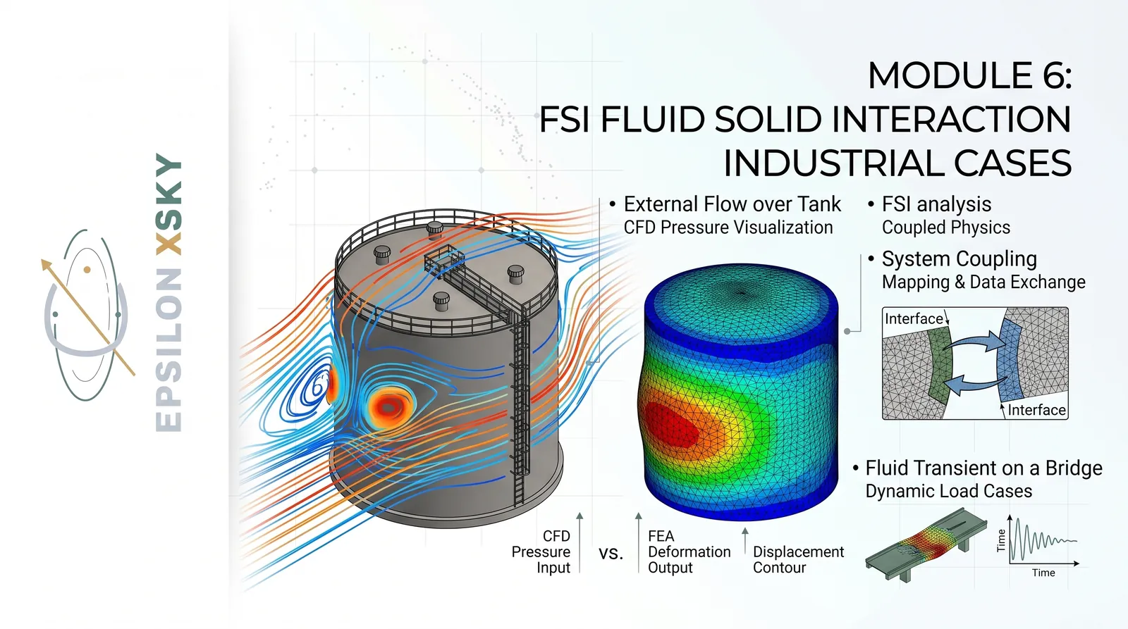
Module 6
FSI Fluid Solid interaction Industrial Cases
3,500 EGPOriginal price: 5,000−30%
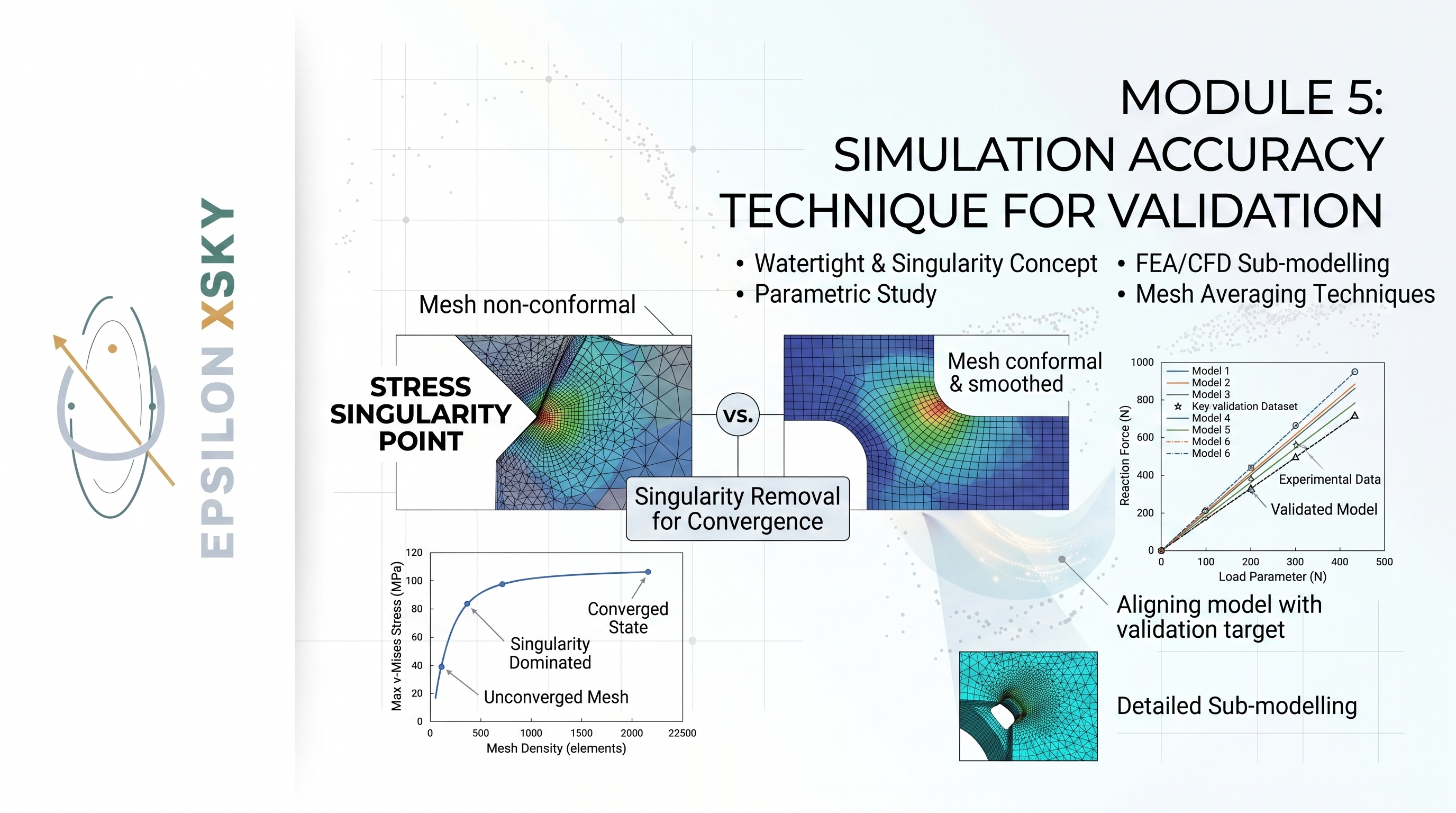
Module 5
Simulation accuracy Technique for Validation
3,000 EGPOriginal price: 6,000−50%
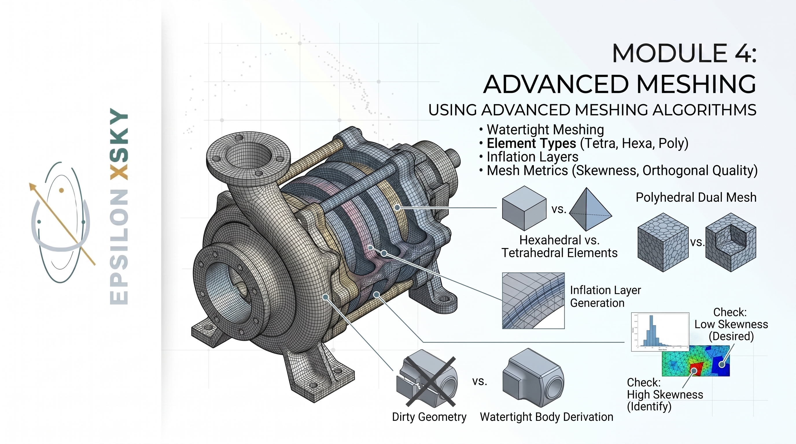
Module 4
Advanced Meshing
3,500 EGPOriginal price: 7,000−50%
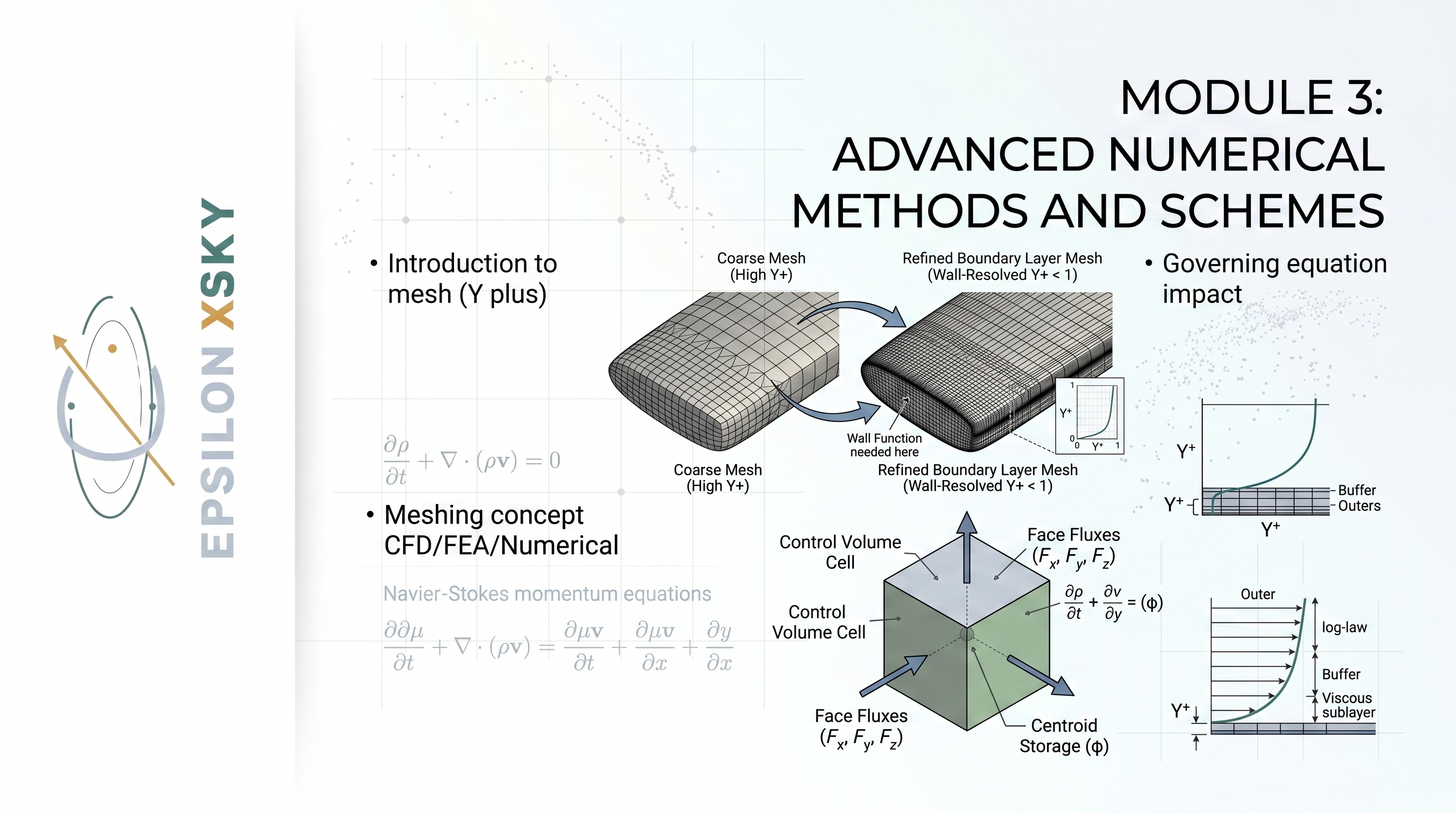
Module 3
Advanced Numerical Methods and Schemes
3,250 EGPOriginal price: 6,500−50%
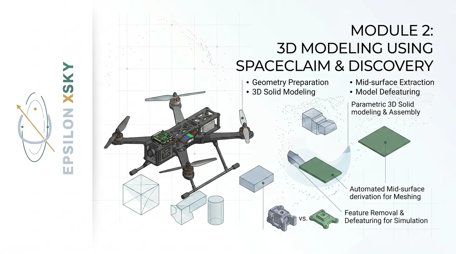
Module 2
3D Modeling using SpaceClaim & Discovery
7,500 EGP
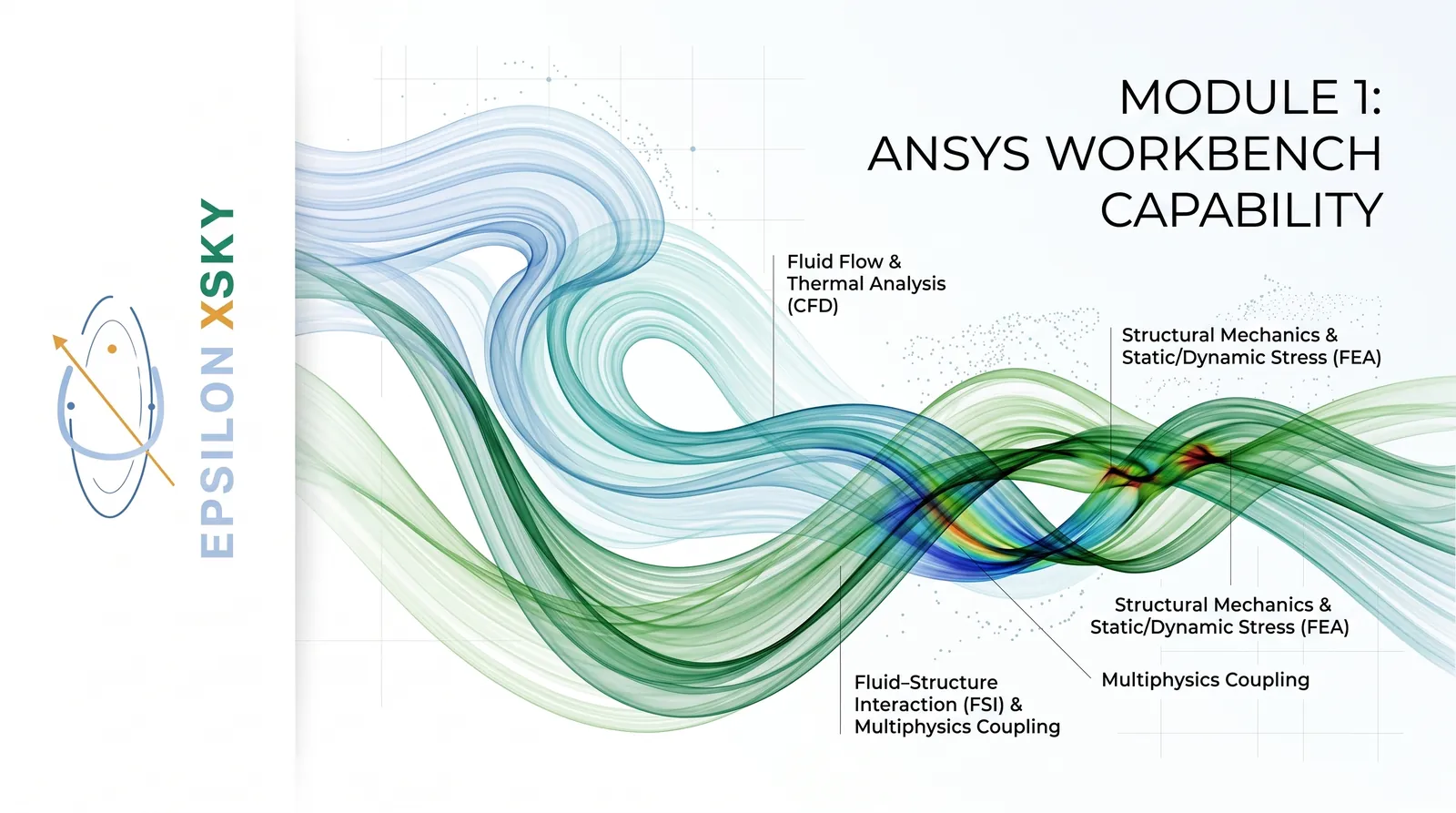
Module 1
ANSYS Workbench Capability
400 EGP
About Industry-Oriented CAE Simulation MasterClass
Industry-Oriented CAE Simulation MasterClass
From CAE Fundamentals to Advanced Multiphysics and Industrial Applications
The Industry-Oriented CAE Simulation MasterClass at Epsilon X Sky is a comprehensive engineering simulation program designed to take participants from the fundamentals of ANSYS and numerical methods to advanced, industry-specific CFD, FEA, multiphysics, optimization, and simulation applications.
The course is structured around 19 progressive modules, combining theoretical foundations with practical industrial case studies. Participants do not simply learn how to operate ANSYS software; they develop the engineering judgment required to select the appropriate physics, solver, numerical approach, modeling strategy, and validation methodology for real engineering problems.
The program covers the complete simulation workflow, starting from ANSYS Workbench and CAD preparation, progressing through advanced meshing, numerical methods, FEA, CFD, FSI, vibration, biomedical, combustion, HVAC, aerospace, turbomachinery, civil engineering, acoustics, automotive, heat transfer, optimization, numerical foundations, and agricultural applications.
Module 1: ANSYS Workbench Capability
Understanding the Complete ANSYS Ecosystem and Engineering Simulation Strategy
This module establishes the fundamental knowledge required to work effectively with the complete ANSYS simulation ecosystem.
Participants begin by exploring the ANSYS Workbench environment and understanding how different simulation systems can be connected within a unified engineering workflow.
The module introduces ANSYS Mechanical and explains its applications in structural, mechanical, nonlinear, dynamic, and vibration analysis.
ANSYS Fluent is introduced as a powerful platform for CFD, heat transfer, multiphase flow, combustion, species transport, and complex fluid-flow applications.
Participants are also introduced to ANSYS CFX and its important applications in turbomachinery and advanced fluid-flow simulations.
The module provides an overview of Polyflow and its specialized applications involving complex fluid behavior and industrial processing.
ANSYS Discovery is introduced as a rapid engineering simulation and design-exploration platform.
Participants also explore Icepak and its applications in electronics cooling and advanced thermal-management problems.
Sherlock is introduced for electronics reliability and life-prediction applications, while SIwave is introduced for PCB and electromagnetic analysis.
An introduction to HFSS provides participants with an overview of high-frequency electromagnetic and antenna simulation.
The module explains the capabilities and limitations of different ANSYS solvers so engineers can select the appropriate tool for a specific engineering problem.
Participants learn the difference between one-way coupling, two-way coupling, System Coupling, and broader multiphysics workflows.
The module explains how CFD, FEA, thermal, electromagnetic, and other physics can interact within complex engineering systems.
Participants study the differences between 1D line-element, 2D shell-element, and 3D solid-element modeling approaches.
The course explains when linear analysis is appropriate and when nonlinear effects such as contact, material behavior, or large deformation must be considered.
Static and dynamic analysis concepts are introduced, allowing participants to understand how time-dependent loading influences engineering simulations.
The fundamental differences between implicit and explicit solvers are explained with reference to their appropriate industrial applications.
Participants are introduced to the governing equations behind the different physics represented by ANSYS solvers.
The module develops an engineering decision-making methodology for selecting the correct physics, solver, modeling approach, and solution strategy.
The complete industrial workflow from CAD preparation through modeling, meshing, simulation, post-processing, validation, and reporting is presented.
By completing this module, participants gain the foundation required to approach advanced CAE problems with a clear understanding of which physics to solve, which solver to use, and why.
Module 2: 3D Modeling Using SpaceClaim & Discovery
Building Simulation-Ready CAD Models Using Industrial Best Practices
This module focuses on preparing high-quality and simulation-ready CAD geometry using ANSYS SpaceClaim and Discovery.
Participants learn why CAD preparation is one of the most important stages in developing an efficient CFD or FEA model.
The module begins with sketching fundamentals and develops the participant's ability to create accurate engineering geometry.
3D solid modeling techniques are introduced for creating components suitable for structural, thermal, and fluid simulations.
Participants also explore surface modeling techniques for complex engineering geometries and specialized simulation applications.
Sheet-metal modeling is introduced for industrial mechanical components and thin-walled structures.
The module explains line-body creation for beam, truss, frame, and other simplified structural models.
Shell-body creation is covered for thin structures where full 3D solid modeling may be unnecessarily expensive.
Participants learn how to extract mid-surfaces from thin-walled components to create efficient shell-based FEA models.
Beam and line-element modeling techniques are introduced for efficient structural analysis of appropriate engineering systems.
Named Selections are explained as an important method for organizing geometry and creating robust simulation workflows.
Topology sharing is introduced to maintain proper connectivity between adjacent bodies and support accurate numerical models.
The module provides practical experience with SpaceClaim repair tools for identifying and correcting problematic geometry.
Participants learn geometry-cleanup techniques that improve mesh generation and reduce solver difficulties.
Simplification and defeaturing techniques are introduced to remove unnecessary geometric details that increase computational cost without contributing significantly to the intended analysis.
The module also introduces parameterization concepts for preparing CAD models for design studies and optimization.
Reverse-engineering fundamentals are discussed to demonstrate how existing physical components can be reconstructed into usable digital geometry.
Industrial applications include a complete quadcopter assembly and structural models such as trusses and electrical transmission towers.
Participants also work conceptually with pressure vessels, piping and plumbing systems, heat exchangers, storage tanks, and industrial support structures.
The module emphasizes the connection between CAD quality, mesh quality, solver efficiency, and final simulation accuracy.
By completing this module, participants will be able to transform complex industrial CAD geometry into clean, simplified, connected, and simulation-ready models.
Module 3: Advanced Meshing
Generating High-Quality Meshes for Accurate Numerical Simulation
This module provides comprehensive training in advanced mesh generation for both CFD and FEA applications.
Participants learn the fundamentals of ANSYS Meshing and understand why mesh quality directly influences numerical accuracy and computational stability.
The module introduces the Watertight Meshing workflow for clean and well-defined CFD geometries.
Fault-Tolerant Meshing is introduced for applications involving more complicated or imperfect geometry.
Participants also explore the Fluent Meshing workflow and its role in advanced industrial CFD applications.
The module explains the differences between tetrahedral, hexahedral, polyhedral, prism, and pyramid elements.
Line, shell, and solid mesh concepts are covered for different structural modeling requirements.
Participants learn how to use global sizing to control overall mesh resolution across an engineering model.
Local sizing techniques are introduced to provide additional resolution in regions where important physical behavior occurs.
Body of Influence is explained as an effective method for controlling mesh refinement within selected regions of a computational domain.
Face and edge sizing techniques are introduced for capturing important geometric and physical features.
Inflation layers are covered in detail because near-wall resolution is critical for many CFD applications.
Participants learn how Y+ requirements influence the selection and quality of boundary-layer mesh strategies.
Curvature and proximity size functions are introduced to ensure sufficient mesh resolution around curved surfaces and closely spaced geometry.
The module covers Sweep, MultiZone, Hex Dominant, Patch Conforming, and Patch Independent mesh-generation methods.
Participants study skewness, orthogonal quality, aspect ratio, and Jacobian as important indicators of mesh quality.
The relationship between mesh quality, number of nodes, degrees of freedom, computational cost, and solution accuracy is explained.
Gaussian integration points are introduced in the context of finite-element calculations and numerical integration.
Mesh independence studies are presented as an essential technique for demonstrating that engineering conclusions are not dependent on insufficient mesh resolution.
Participants learn practical mesh-optimization techniques that balance computational efficiency with the accuracy required by the engineering problem.
By completing this module, engineers will be able to develop physics-aware, application-specific meshes rather than simply generating a visually acceptable mesh.
Module 4: Advanced Numerical Methods & Schemes
Understanding How Governing Equations Become Numerical Solutions
This module introduces the numerical foundations required to understand how CFD and heat-transfer solvers convert physical equations into computational solutions.
Participants begin by studying the relationship between computational meshes and numerical methods.
The concept of Y+ is introduced to demonstrate how mesh resolution near walls influences the treatment of turbulent boundary layers.
The module examines the fundamental differences between meshing requirements for CFD and FEA simulations.
Participants learn why the same geometry may require very different mesh strategies depending on the governing physics being solved.
The relationship between mesh size, discretization, numerical accuracy, and computational cost is explored.
The continuity equation is studied from the perspective of numerical CFD and its relationship with mass conservation across computational cells.
The momentum equations are introduced to demonstrate how fluid motion and momentum transport are represented numerically.
The energy equation is examined in relation to temperature, heat transfer, and thermal-energy transport.
Participants study the Finite Volume Method and understand how it is used to solve conservation equations in industrial CFD.
The module explains how governing equations are integrated over control volumes within the computational domain.
Participants learn how surface fluxes connect neighboring computational cells and contribute to conservation.
The process of transforming differential governing equations into algebraic equations is explained step by step.
The module demonstrates how numerical schemes influence the accuracy, stability, and convergence of CFD solutions.
Participants explore the relationship between governing equations, mesh characteristics, discretization methods, and solver behavior.
The effect of numerical choices on pressure, velocity, temperature, and other engineering variables is discussed.
A numerical solution of the 1D heat-conduction equation is introduced to demonstrate how a continuous physical problem can be converted into a discrete computational system.
The case study helps participants understand the relationship between mathematical formulation and practical numerical implementation.
The module also develops an understanding of why mesh refinement alone cannot guarantee an accurate result if the numerical formulation is inappropriate.
Participants learn to view CFD as a combination of physics, mathematical equations, discretization, numerical schemes, and iterative solution techniques.
By completing this module, engineers gain a stronger foundation for understanding and diagnosing numerical behavior inside industrial CFD simulations.
Module 5: Simulation Accuracy Techniques for Validation
Developing Reliable, Accurate, and Engineering-Relevant Simulation Results
This module focuses on one of the most important aspects of CAE: determining whether a simulation result is sufficiently accurate and reliable for engineering decision-making.
Participants begin by studying the concept of watertight geometry and understanding how geometry defects can affect numerical simulation.
Singularity concepts are introduced to explain regions where conventional numerical results may become highly sensitive or theoretically problematic.
Participants investigate the relationship between singularities and parametric studies and learn how to distinguish physical behavior from numerical artifacts.
The module introduces parametric studies as a systematic method for evaluating the sensitivity of simulation results to changes in important parameters.
Participants learn how simulation accuracy can be investigated through controlled variations in geometry, material properties, boundary conditions, and operating conditions.
FEA parametric-study techniques are explored using engineering-oriented structural applications.
CFD parametric studies are introduced to investigate how flow behavior and numerical results change when important simulation variables are modified.
The module emphasizes that a single simulation result should not automatically be considered the correct engineering answer.
Participants learn how to evaluate whether results are sufficiently independent of mesh resolution and numerical settings.
Averaging and unaveraging techniques are introduced to help engineers understand how post-processing choices can influence the interpretation of FEA results.
The module explains the importance of examining both raw and processed simulation data when evaluating critical engineering regions.
FEA sub-modeling techniques are introduced as a method for obtaining high-resolution information in critical local regions without unnecessarily increasing the computational cost of the complete model.
CFD sub-modeling concepts are also introduced for applications where localized flow behavior requires additional resolution.
Participants learn how sub-modeling can be used as part of an industrial simulation strategy.
The module emphasizes the relationship between mesh quality, model assumptions, numerical settings, post-processing, and engineering accuracy.
Participants develop a structured approach for checking whether a simulation is converged and whether the resulting engineering conclusions are robust.
The module also introduces practical strategies for improving Fluent simulations when accurate and stable results are required.
Validation and accuracy are presented as continuous processes rather than steps performed only after the simulation has finished.
By completing this module, participants will be better equipped to distinguish between a simulation that produces numbers and a simulation that produces trustworthy engineering information.
Module 6: FSI – Fluid–Structure Interaction Industrial Cases
Advanced Fluid–Structure Interaction and System Coupling
This module introduces Fluid–Structure Interaction (FSI) as one of the most important multiphysics applications in modern engineering simulation.
Participants learn how fluid flow can generate pressure and forces that influence structural deformation and how structural deformation can subsequently affect the surrounding fluid.
The module begins with an external-flow analysis around a tank to establish the CFD foundation required for coupled fluid–structure simulations.
Participants learn how to define the fluid domain, generate an appropriate computational mesh, establish boundary conditions, and analyze the resulting flow field.
The analysis then progresses toward structural modeling, where fluid pressure loads are transferred to the structural model.
Participants explore FSI concepts from both the CFD and FEA perspectives and understand how the two domains exchange information.
A dedicated FSI tank case demonstrates how pressure distribution generated by the fluid can influence the structural response of the tank.
The module introduces transient FSI problems where fluid loads and structural behavior change with time.
Participants study the principles of System Coupling and learn how different ANSYS solvers can communicate during a coupled simulation.
A real bridge transient System Coupling application is introduced to demonstrate how fluid-induced loading can affect a large engineering structure.
Participants learn how transient pressure, structural deformation, velocity, and other physical quantities can be exchanged between simulation systems.
The module explains the difference between one-way FSI and fully coupled two-way FSI.
Participants learn when a one-way approach may be sufficient and when two-way coupling is required because structural deformation significantly affects the fluid domain.
Fluent setup procedures for FSI applications are introduced, including the preparation of the fluid model and appropriate boundary conditions.
The module also discusses the importance of time-step selection, convergence, mesh quality, and data-transfer settings in coupled simulations.
Participants learn how to monitor both fluid and structural convergence during a coupled analysis.
The interaction between fluid forces, structural response, and numerical stability is examined throughout the industrial cases.
The module demonstrates how FSI can be applied to tanks, bridges, fluid systems, flexible structures, and other engineering applications.
Participants develop the ability to understand and construct complete FSI workflows using CFD, FEA, and System Coupling.
By completing this module, engineers gain practical knowledge of how fluid physics and structural mechanics can be solved together to predict real multiphysics behavior.
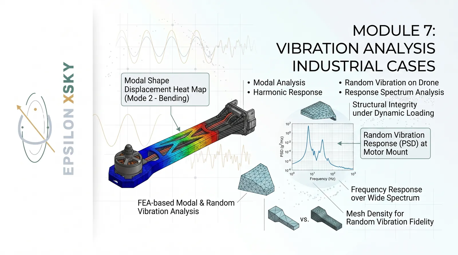
Module 7: Vibration Analysis – Industrial Cases
Advanced Structural Dynamics and Industrial Vibration Simulation
This module focuses on the application of FEA to real-world vibration and structural-dynamics problems.
Participants begin with Modal Analysis and learn how natural frequencies and mode shapes are calculated for engineering structures.
The module explains why natural frequencies are important when evaluating the dynamic reliability of mechanical systems.
Participants learn how boundary conditions, material properties, geometry, and structural stiffness influence modal behavior.
Prestressed Modal Analysis is introduced for systems where an existing structural stress state influences subsequent vibration behavior.
The module then progresses to Harmonic Response Analysis for structures subjected to sinusoidal or frequency-dependent excitation.
Participants learn how to generate frequency-response curves and identify regions where resonance may occur.
A dedicated drone modal-analysis project demonstrates how FEA can be used to investigate the dynamic characteristics of lightweight aerospace structures.
Participants analyze the natural frequencies and mode shapes of drone components and learn how the results can support structural design decisions.
A complete washing-machine harmonic-analysis project introduces a realistic industrial vibration problem involving rotating and periodic excitation.
Participants investigate how operating frequencies can interact with structural modes and generate significant dynamic response.
Random Vibration Analysis is introduced for systems exposed to stochastic or broadband excitation.
The module explains concepts associated with Power Spectral Density and statistical structural response.
Participants also study Response Spectrum Analysis and its applications in engineering structures subjected to dynamic loading.
A Random Vibration analysis of a drone arm provides another practical example of vibration evaluation for lightweight structures.
Participants learn how to interpret deformation, stress, acceleration, and frequency-response results.
The module emphasizes the relationship between excitation frequency, structural natural frequencies, damping, and resonance.
Practical techniques for identifying potentially dangerous operating ranges are discussed throughout the case studies.
The module prepares engineers to use FEA for vibration prediction, structural reliability assessment, and dynamic design improvement.
By completing this module, participants gain a practical understanding of how FEA can predict and diagnose vibration behavior before problems appear in physical prototypes.
Module 8: Biomedical Engineering – Industrial Cases
CFD Applications in Biomedical Engineering
This module introduces the application of computational simulation to biomedical engineering through a practical blood-flow CFD case study.
Participants explore how CFD principles can be applied to biological fluid systems where flow behavior is influenced by complex geometry and operating conditions.
The module begins by introducing the physical characteristics of blood as an engineering fluid and discussing the challenges associated with biomedical CFD.
Participants learn how an anatomical or biomedical geometry can be prepared for computational analysis.
The geometry-preparation stage includes identifying the fluid domain and creating a suitable representation for numerical simulation.
Participants learn how to develop an appropriate mesh capable of resolving important flow features within the biomedical domain.
Boundary conditions are introduced based on realistic flow conditions and the requirements of the biomedical application.
The module demonstrates how CFD can be used to calculate velocity distributions within a blood-flow system.
Pressure distributions are also analyzed to identify regions of significant pressure variation.
Participants investigate how geometry can influence flow separation, recirculation, and local flow behavior.
The relationship between flow patterns and biomedical engineering performance is discussed throughout the case study.
Participants learn how to use CFD post-processing tools to visualize and interpret complex biological flow fields.
The module also emphasizes the importance of numerical accuracy when working with sensitive biomedical simulation results.
Mesh quality, convergence, boundary conditions, and physical assumptions are discussed as critical components of reliable biomedical CFD.
The blood-flow project provides an example of how conventional CFD methodologies can be adapted to specialized engineering applications.
Participants gain an understanding of how simulation can support biomedical research, device development, and flow-system analysis.
The module demonstrates the multidisciplinary nature of biomedical simulation, combining fluid mechanics, numerical methods, geometry, and biological considerations.
Engineers learn how to interpret CFD results from an engineering perspective rather than simply producing graphical contours.
The case study also provides a foundation for future biomedical applications involving cardiovascular systems and medical devices.
Participants develop a practical understanding of the workflow required to move from biomedical geometry to a complete CFD solution.
By completing this module, engineers gain experience applying industrial CFD methodology to complex biomedical fluid-flow problems.
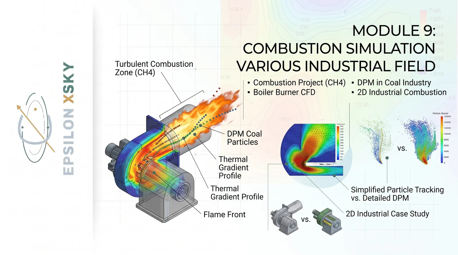
Module 9: Combustion Simulation – Industrial Applications
Advanced CFD Modeling of Combustion and Reacting Flows
This module introduces advanced CFD techniques for analyzing combustion systems across different industrial applications.
Participants begin with a combustion project involving CH₄ species, providing an introduction to reacting-flow simulation.
The project demonstrates how CFD can be used to predict species transport, temperature distribution, velocity fields, and combustion behavior.
Participants learn how combustion simulations differ from conventional non-reacting CFD because additional physical and chemical processes must be considered.
The module introduces species transport concepts and explains how multiple chemical species are represented within the computational domain.
A dedicated industrial boiler-burner CFD project demonstrates how simulation can support the analysis of practical combustion equipment.
Participants investigate flow behavior, mixing, combustion regions, temperature distribution, and the overall behavior of the burner system.
The module also introduces the challenges associated with obtaining stable and accurate solutions for highly nonlinear reacting flows.
Participants study how mesh quality, boundary conditions, operating conditions, and numerical settings influence combustion results.
A coal-industry project introduces Discrete Phase Modeling for applications involving solid particles within a reacting flow.
Participants learn how particle trajectories and interactions with the continuous fluid phase can be represented computationally.
The DPM case provides practical insight into industrial applications involving coal particles and combustion systems.
The module also introduces a 2D industrial combustion approach for understanding the fundamental behavior of reacting systems with reduced geometric complexity.
Participants learn how simplified models can be useful for studying fundamental physical behavior before progressing to more complex 3D simulations.
Temperature, velocity, pressure, and species distributions are analyzed during post-processing.
The module emphasizes the importance of monitoring convergence and validating combustion predictions against appropriate engineering expectations or experimental information.
Participants learn how CFD can be used to identify combustion zones, thermal behavior, flow patterns, and potential design limitations.
The industrial cases demonstrate how combustion simulation can support the development and optimization of burners, boilers, and energy systems.
By completing this module, engineers gain a practical foundation for CFD simulation of industrial reacting flows, combustion systems, and particle-laden combustion applications.
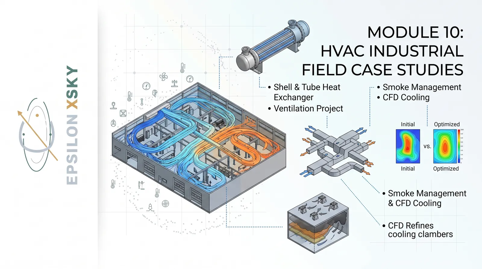
Module 10: HVAC – Industrial Field Case Studies
CFD for HVAC, Ventilation, Cooling, and Smoke Management
This module focuses on applying CFD to real HVAC and thermal-management engineering problems.
Participants learn how CFD can be used to investigate airflow distribution, temperature fields, ventilation effectiveness, and thermal performance.
The module begins with a Shell & Tube Heat Exchanger CFD project, introducing the analysis of fluid flow and heat transfer inside an industrial thermal system.
Participants investigate temperature distribution, velocity fields, pressure variation, and heat-transfer behavior within the exchanger.
The module then progresses to a garage-ventilation project where CFD is used to analyze airflow distribution within an enclosed space.
Participants identify areas with insufficient ventilation and investigate how inlet and outlet configurations influence air circulation.
An AC-room CFD case study introduces thermal comfort and indoor-airflow concepts.
Participants analyze temperature distribution, airflow patterns, cooling effectiveness, and potential hot or cold regions within the room.
The module also introduces a Smoke Management Project using CFD to investigate the movement of smoke within an enclosed environment.
Participants learn how smoke propagation can be analyzed to support safer ventilation and smoke-control strategies.
A CFD cooling heat-source project demonstrates how airflow can be used to remove heat from localized sources.
Participants investigate the interaction between heat generation, fluid movement, temperature distribution, and cooling effectiveness.
The module also includes a thermostat heat-exchanger application to demonstrate thermal control within an engineering system.
Participants learn how boundary conditions and operating conditions can influence the resulting thermal behavior.
The module emphasizes the importance of proper geometry preparation, mesh quality, turbulence modeling, energy modeling, and convergence monitoring.
Participants develop skills in extracting temperature, velocity, pressure, heat-transfer, and airflow information from CFD results.
The industrial cases demonstrate how CFD can support HVAC design, ventilation optimization, thermal management, and smoke-control engineering.
The module connects fundamental heat-transfer and fluid-flow principles with practical building and industrial applications.
Participants learn how to identify inefficient airflow regions and develop simulation-based recommendations for improved system performance.
By completing this module, engineers will be able to approach HVAC problems using a structured CFD workflow from geometry and meshing through thermal analysis and engineering interpretation.
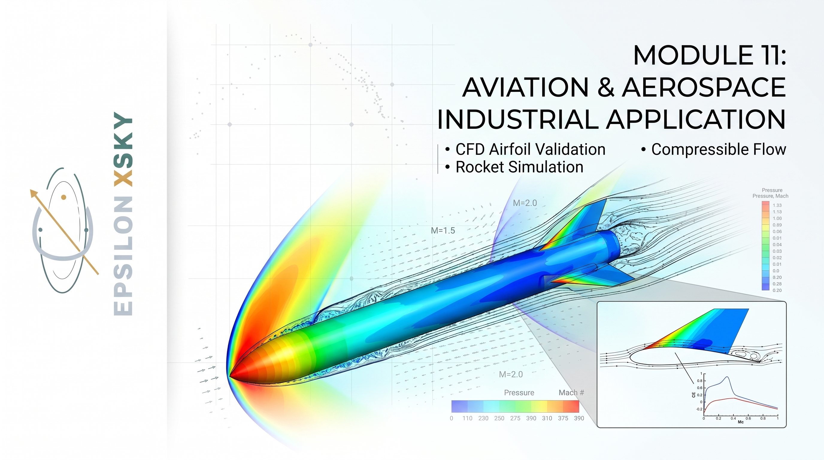
Module 11: Aviation & Aerospace – Industrial Applications
Advanced CFD for Airfoils, UAVs, Rockets, and Compressible Aerodynamics
This module focuses on the application of CFD to challenging aviation and aerospace engineering problems.
Participants begin with aerodynamic analysis of airfoils and learn how CFD can be used to investigate the interaction between airflow and aerodynamic surfaces.
The module covers the complete CFD workflow for an airfoil, including geometry preparation, computational-domain creation, meshing, boundary conditions, solver setup, convergence, and post-processing.
Participants analyze velocity, pressure, streamline, wall-shear, and aerodynamic-force distributions around the airfoil.
Airfoil CFD results are studied in detail to help engineers understand how aerodynamic performance can be extracted from numerical simulations.
The module also introduces CFD validation for airfoil simulations and explains how numerical predictions can be compared with appropriate reference or experimental data.
Participants learn why validation is essential before using CFD results for engineering design decisions.
The course progresses toward a complete quadcopter CFD simulation, providing practical experience with a realistic aerospace configuration.
Participants investigate the complex aerodynamic flow around a quadcopter and learn how multiple aerodynamic components interact with the surrounding air.
The quadcopter project demonstrates how CFD can support UAV aerodynamic development and performance evaluation.
The module then introduces rocket CFD simulation, exposing participants to the aerodynamic challenges associated with high-speed aerospace vehicles.
Participants study pressure distribution, velocity fields, flow structures, and aerodynamic forces around rocket geometries.
Compressible-flow CFD is also introduced through an airfoil application to demonstrate how density changes become important at higher flow speeds.
Participants learn why compressibility can significantly influence pressure, velocity, density, and aerodynamic performance.
The module emphasizes appropriate boundary conditions, mesh quality, turbulence modeling, convergence, and numerical stability for aerospace applications.
Participants develop practical skills in interpreting aerodynamic coefficients and identifying important flow structures.
The industrial cases demonstrate how CFD can support the design and analysis of airfoils, UAVs, rockets, and other aerospace systems.
The module connects aerodynamic theory with practical numerical simulation and engineering decision-making.
By completing this module, engineers gain a structured approach to aerospace CFD from basic airfoil analysis to complete UAV, rocket, and compressible-flow simulations.
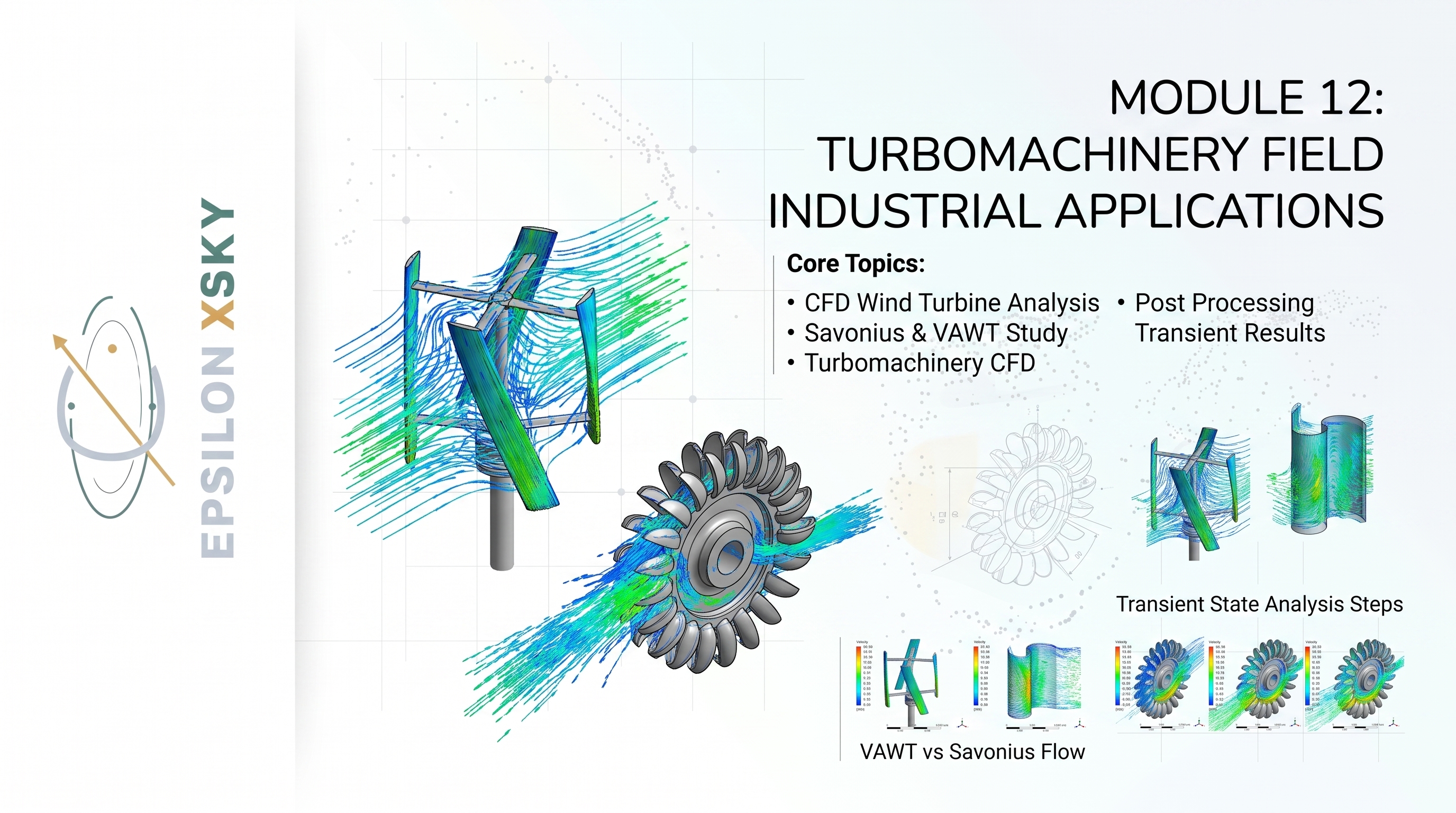
Module 12: Turbomachinery – Industrial Applications
CFD Analysis of Wind Turbines, VAWT, Savonius, and Pelton Turbines
This module focuses on CFD applications involving rotating machinery, renewable-energy systems, and turbomachinery.
Participants begin with CFD analysis of a wind turbine and investigate how airflow interacts with rotating blades to generate aerodynamic forces and useful power.
The module introduces the fundamental flow structures associated with rotating machinery, including pressure differences, velocity fields, wake formation, and vortex structures.
Participants explore the Savonius wind turbine as a practical example of a vertical-axis renewable-energy system.
The analysis investigates how the rotating blades interact with the surrounding flow and how their geometry influences performance.
The module then progresses to Vertical Axis Wind Turbine (VAWT) CFD analysis, introducing the challenges associated with highly unsteady rotating flows.
Participants learn how transient CFD can be used to capture changing aerodynamic forces as the blades rotate through different positions.
A VAWT validation and analysis case demonstrates how numerical results can be evaluated against suitable reference information.
Participants study performance indicators such as torque, pressure distribution, velocity, and other relevant aerodynamic quantities.
The module introduces turbomachinery CFD concepts and explains the importance of appropriate rotating-domain and transient-simulation strategies.
Participants learn how to prepare and analyze transient turbomachinery results and extract meaningful engineering information from time-dependent data.
Advanced post-processing techniques are introduced to visualize periodic behavior and identify important flow structures.
The module also includes a Pelton wheel turbine CFD study, providing an application involving water-driven turbine behavior.
Participants investigate the interaction between fluid flow and turbine geometry and examine how CFD can support hydraulic-performance evaluation.
The module emphasizes mesh quality, time-step selection, convergence, rotating reference frames, and transient solution requirements.
Participants learn how to compare different turbine designs and operating conditions from an engineering-performance perspective.
The industrial applications demonstrate the broad use of CFD in wind energy, hydraulic turbines, and rotating machinery.
The module connects fluid mechanics, transient CFD, rotating flows, and energy-conversion principles.
Participants develop the ability to interpret complex turbomachinery flow fields and convert simulation results into engineering conclusions.
By completing this module, engineers gain practical experience in CFD analysis of renewable-energy and turbomachinery systems.
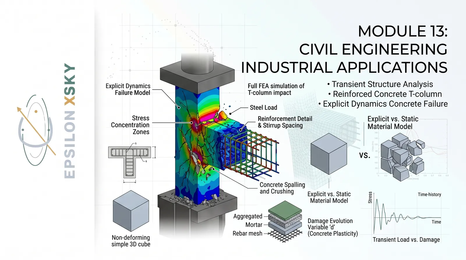
Module 13: Civil Engineering – Industrial Applications
Advanced FEA for Transient Structures, Reinforced Concrete, and Failure Analysis
This module introduces advanced FEA applications for civil and structural engineering problems.
Participants begin with transient structural analysis and learn how structures respond to loads that change with time.
The module includes two dedicated transient structural projects that demonstrate practical approaches to modeling dynamic structural behavior.
Participants learn how geometry, material properties, constraints, loading conditions, and time integration influence structural results.
The module then introduces reinforced-concrete analysis through a dedicated reinforced concrete T-column project.
Participants investigate the structural behavior of reinforced concrete under applied loading and explore the interaction between concrete and reinforcement.
The project provides an introduction to nonlinear structural behavior and the challenges involved in simulating realistic civil-engineering materials.
The module progresses toward Explicit Dynamics through a dedicated crush-test project.
Participants learn how explicit numerical methods can be used to simulate highly nonlinear events involving large deformation and rapid changes in structural behavior.
The crush-test project demonstrates how FEA can be applied to evaluate deformation, stress, energy absorption, and structural failure.
A dedicated concrete-failure case introduces explicit dynamics for analyzing extreme loading and nonlinear concrete behavior.
Participants investigate how concrete can deform, crack, crush, and ultimately fail under severe loading conditions.
The module emphasizes appropriate material models and the importance of selecting physically meaningful parameters for nonlinear civil-engineering simulations.
Participants learn how mesh resolution can influence the representation of localized deformation and failure.
Contact, large deformation, nonlinear behavior, and transient effects are discussed in relation to explicit structural simulations.
The module demonstrates how simulation can reduce dependence on purely experimental approaches during structural development.
Participants learn to interpret stress, strain, deformation, energy, and failure-related simulation results.
The industrial projects provide practical examples of how advanced FEA can support civil infrastructure and structural engineering.
The module emphasizes the importance of validating numerical assumptions when dealing with complex nonlinear materials.
Participants develop a structured workflow for setting up, solving, and interpreting advanced civil-engineering FEA problems.
By completing this module, engineers gain practical knowledge of transient structural analysis, reinforced-concrete modeling, explicit dynamics, and structural failure simulation.
Module 14: Acoustic Analysis – Industrial Applications
FEA Acoustics and Aeroacoustic Analysis of Industrial Systems
This module introduces computational acoustics and demonstrates how numerical simulation can be used to investigate engineering noise problems.
Participants begin with an acoustic FEA project designed to introduce the fundamental concepts of acoustic pressure and sound propagation.
The module explains how acoustic domains can be represented numerically and how acoustic pressure varies throughout an engineering system.
Participants study acoustic modes and investigate how resonance can influence the acoustic response of a system.
The relationship between structural vibration and acoustic behavior is introduced to demonstrate the multidisciplinary nature of engineering noise analysis.
Participants learn how frequency-dependent acoustic results can be interpreted to identify important operating conditions.
The module then progresses toward aeroacoustic analysis of a propeller, connecting aerodynamic flow behavior with noise generation.
Participants investigate airflow around rotating propeller blades and examine pressure and velocity variations generated by the aerodynamic flow.
The project introduces the relationship between rotating blades, transient flow structures, pressure fluctuations, and aerodynamic noise.
Participants learn why transient CFD information can be important when investigating aeroacoustic behavior.
Wake structures and aerodynamic flow features are examined as potential contributors to noise generation.
The module demonstrates how CFD results can provide information about aerodynamic sources that may subsequently contribute to acoustic behavior.
Participants explore the relationship between CFD, FEA, structural dynamics, and acoustic simulation.
The module emphasizes appropriate mesh resolution, transient time-step selection, convergence, and data quality for acoustic applications.
Participants learn how to interpret acoustic pressure and frequency-domain results from an engineering perspective.
The industrial cases demonstrate how simulation can support noise prediction and reduction in rotating and mechanical systems.
Applications can extend to propellers, fans, turbomachinery, automotive components, aerospace systems, and industrial machinery.
The module develops an understanding of how noise can be treated as a physical engineering problem rather than simply a measurement problem.
Participants learn how simulation can help identify potential noise sources before physical prototypes are manufactured.
The module provides an industry-oriented introduction to combining aerodynamic and structural simulation concepts with acoustic analysis.
By completing this module, engineers gain practical knowledge of FEA acoustic analysis and CFD-based aeroacoustic investigation.
Module 15: Automotive Engineering – Industrial Application
Formula Car CFD and Advanced Automotive Aerodynamic Analysis
This module focuses on the application of CFD to high-performance automotive aerodynamics through a dedicated Formula Car CFD project.
Participants learn how external aerodynamic simulations can be used to investigate airflow around a complete vehicle.
The module begins with preparation of the automotive geometry and development of an appropriate computational domain.
Participants learn how to generate a mesh capable of capturing important aerodynamic features around the vehicle.
Boundary conditions and operating conditions are introduced for external automotive flow simulations.
The CFD analysis investigates velocity distribution around the vehicle and identifies important flow structures.
Participants examine surface pressure distribution to understand how aerodynamic loading is generated.
The module focuses on the aerodynamic forces acting on the Formula car, particularly drag and downforce.
Participants learn how aerodynamic coefficients can be extracted and used to compare different vehicle configurations.
The influence of the front wing, rear wing, bodywork, floor, diffuser, wheels, and other aerodynamic components is discussed.
Participants investigate flow separation and recirculation regions that can negatively influence aerodynamic performance.
Wake formation behind the vehicle is analyzed to understand how the car modifies the surrounding airflow.
The module demonstrates how vortices and complex three-dimensional flow structures develop around a high-performance vehicle.
Participants learn how pressure and velocity contours can be converted into meaningful aerodynamic engineering conclusions.
The relationship between downforce, drag, vehicle stability, and aerodynamic efficiency is examined.
The module emphasizes the importance of mesh quality and numerical settings when predicting aerodynamic forces accurately.
Participants learn how CFD can be used to identify areas where aerodynamic geometry may require further optimization.
The Formula Car case demonstrates how simulation can support performance-oriented automotive design.
The methodology can also be extended to passenger vehicles, electric vehicles, sports cars, commercial vehicles, and autonomous vehicles.
Participants develop a complete automotive CFD workflow from geometry preparation through aerodynamic post-processing.
By completing this module, engineers gain practical experience in automotive external-flow CFD, aerodynamic-force analysis, wake investigation, and performance-oriented design evaluation.
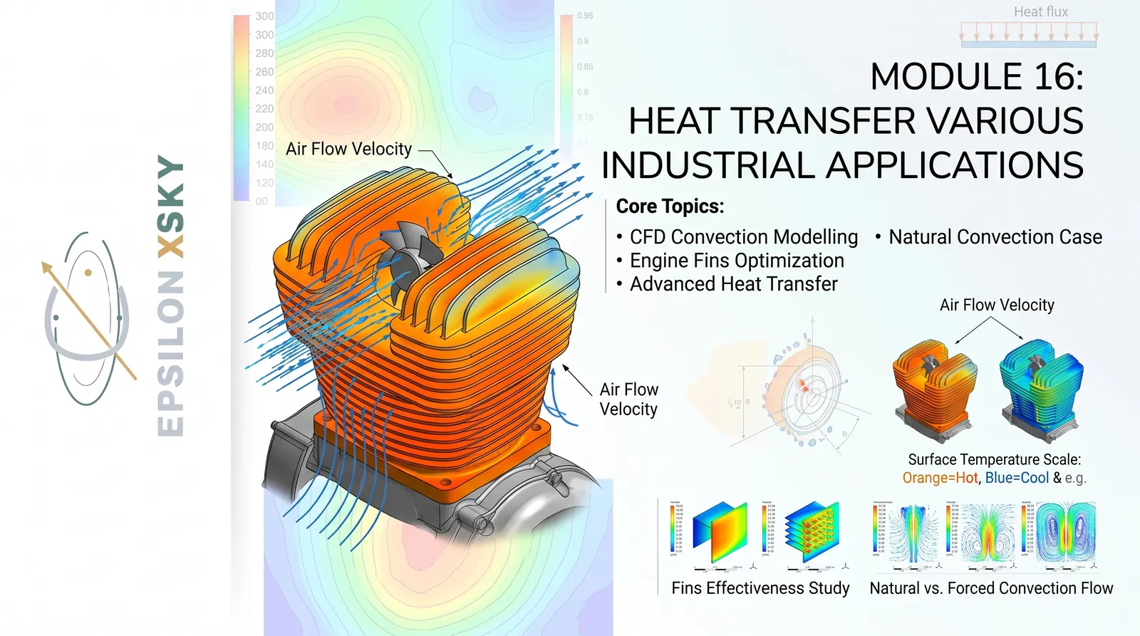
Module 16: Heat Transfer – Industrial Applications
Module 16 focuses on advanced CFD-based thermal analysis for real industrial engineering problems.
Participants begin by understanding the fundamental mechanisms responsible for heat generation and thermal transport.
The module explains how heat is transferred through conduction, convection, and radiation within engineering systems.
Special attention is given to convection because of its importance in cooling systems and industrial thermal management.
Participants investigate how temperature differences influence fluid motion and heat-transfer performance.
The module introduces practical methods for defining thermal boundary conditions in ANSYS CFD simulations.
Participants learn how heat sources can be represented within solid and fluid computational domains.
The module includes an industrial engine-fin optimization project based on CFD simulation.
The engine-fin project demonstrates how temperature distributions can be predicted throughout a thermally loaded component.
Participants analyze airflow around engine fins and evaluate the resulting cooling behavior.
The simulation is used to determine local and average heat-transfer rates across the finned surfaces.
Participants investigate how fin geometry can influence temperature reduction and thermal efficiency.
Different geometric parameters can be evaluated to determine their influence on cooling performance.
The module introduces the concept of thermal resistance and its relationship to overall heat-transfer performance.
Participants also study mesh requirements for accurate temperature and heat-flux predictions.
The natural-convection section introduces buoyancy-driven flow caused by density variations resulting from temperature differences.
Participants learn how gravitational effects can be incorporated into CFD models involving natural convection.
The interaction between temperature fields and velocity fields is investigated through coupled thermal-fluid simulations.
The module introduces conjugate heat transfer, where heat conduction in solids is coupled with convection in surrounding fluids.
Participants learn how conjugate simulations can represent realistic industrial cooling systems more accurately.
Post-processing techniques are used to evaluate temperature contours, heat flux, velocity fields, and heat-transfer coefficients.
The module demonstrates how CFD can be used to compare alternative thermal-management configurations.
Participants learn how simulation results can support engineering decisions before expensive physical prototypes are manufactured.
The final objective is to develop the ability to optimize industrial cooling systems using accurate CFD-based thermal analysis.
Module 17: Parametrization & Optimization – ROM, DOE & optiSLang
Module 17 introduces simulation-driven engineering design optimization using ANSYS optiSLang.
Participants learn how engineering parameters can be connected directly to numerical simulation workflows.
The module begins with the concept of parametrization and explains how geometry and simulation inputs can become design variables.
Participants learn how to identify the parameters that have the greatest influence on engineering performance.
The module introduces Design of Experiments, commonly known as DOE, as a systematic method for exploring design spaces.
Participants investigate how multiple design variables can be varied efficiently without manually running every possible combination.
The module explains how DOE results can reveal relationships between input parameters and simulation outputs.
Sensitivity analysis is introduced to determine which parameters have the strongest influence on the selected performance indicators.
Participants learn how to distinguish important design variables from parameters with limited influence on the final result.
The module introduces response surfaces as mathematical approximations of expensive simulation models.
Participants learn how response surfaces can be used to predict system behavior without running a full high-fidelity simulation for every design point.
Reduced Order Modeling, or ROM, is introduced as a technique for accelerating simulation-based engineering studies.
The module explains how reduced models can approximate complex physical systems while significantly reducing computational cost.
Participants build a complete optiSLang workflow connecting engineering parameters with automated simulation processes.
The workflow demonstrates how multiple simulations can be executed automatically according to predefined design points.
Participants analyze simulation outputs and use statistical and numerical techniques to understand design behavior.
The module then progresses from design exploration toward automated engineering optimization.
Participants define objective functions, constraints, and design variables according to the requirements of the engineering problem.
optiSLang is used to identify promising configurations within the defined design space.
The optimized configuration is then evaluated using the original high-fidelity simulation model.
Participants compare the optimized design against the original baseline configuration.
The comparison demonstrates whether the optimization process produced measurable improvements in engineering performance.
The module also emphasizes validation because an optimization result must be verified using a reliable high-fidelity simulation.
By the end of the module, participants understand how automated simulation workflows can transform engineering design from trial-and-error into a systematic optimization process.
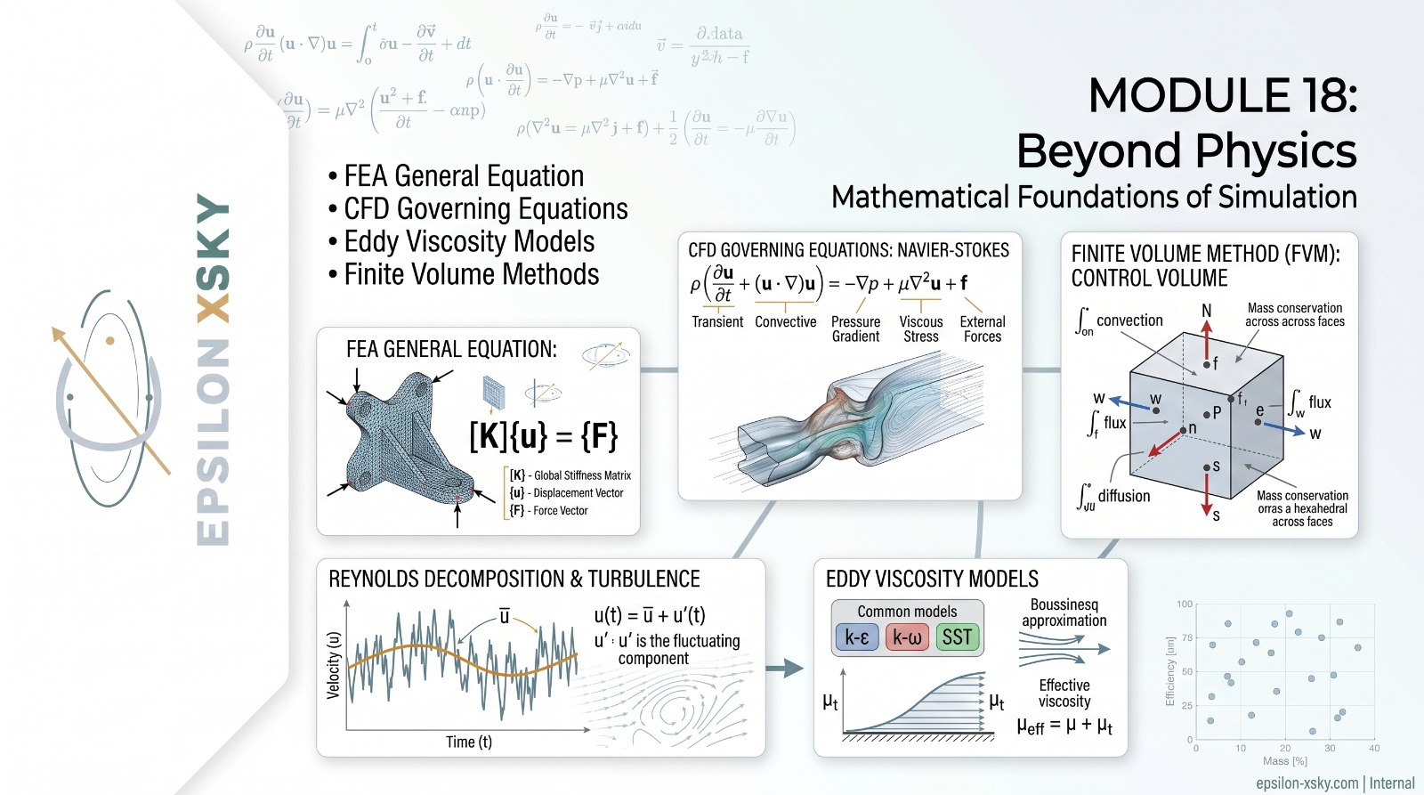
Module 18: Beyond Physics – Numerical & Computational Foundations
Module 18 moves beyond software operation and introduces the mathematical and numerical foundations behind modern CAE simulations.
The objective is to help participants understand what commercial FEA and CFD solvers are actually calculating.
The module begins with the general equations used in finite element analysis and their relationship to physical engineering problems.
Participants study how governing equations are transformed into mathematical systems that can be solved computationally.
The FEA section explains the general solution sequence from physical model definition to discretization and numerical solution.
Participants investigate the relationship between element formulation, degrees of freedom, stiffness matrices, and system equations.
The module then introduces the fundamental governing equations used in computational fluid dynamics.
Participants study the continuity equation and the conservation equations for momentum and energy.
The relationship between conservation laws and the numerical representation of fluid flow is examined.
The module introduces Reynolds decomposition as an important concept in the mathematical treatment of turbulent flows.
Participants learn how instantaneous flow variables can be separated into mean and fluctuating components.
The role of turbulence modeling is then introduced through the concept of eddy-viscosity models.
Participants study why turbulence models are required and how additional modeling assumptions affect CFD predictions.
The module provides an introduction to the Finite Volume Method used by many industrial CFD solvers.
Participants learn how computational domains are divided into control volumes and how conservation equations are applied to these volumes.
The treatment of fluxes across control-volume faces is explained as part of the discretization process.
The module introduces numerical solution techniques including the Gauss-Seidel iterative method.
Participants learn how iterative algorithms progressively reduce the error in numerical solutions.
The relationship between residuals, convergence criteria, numerical stability, and solution accuracy is discussed.
Mesh quality is examined through parameters such as aspect ratio and their potential influence on numerical accuracy.
Participants learn why poor mesh quality can create convergence difficulties or introduce numerical errors.
The module connects mathematical formulation, discretization, numerical algorithms, mesh quality, and solver convergence into one complete computational workflow.
The final objective is to enable engineers to diagnose simulation problems based on numerical principles rather than simply changing solver settings randomly.
After completing the module, participants have a stronger theoretical foundation for understanding the limitations and capabilities of commercial CAE software.
Module 19: Agriculture – Industrial Application
Module 19 demonstrates how CFD can be applied to agricultural engineering through a practical industrial agricultural-nozzle case study.
Participants investigate the internal and external flow behavior associated with an agricultural spray nozzle.
The project begins by defining the geometry and operating conditions of the agricultural nozzle system.
Participants learn how inlet pressure, flow rate, nozzle geometry, and outlet conditions influence the resulting flow field.
The CFD model is used to calculate pressure distribution throughout the nozzle.
Velocity contours are analyzed to identify acceleration, deceleration, recirculation, and high-velocity regions.
Participants investigate how the internal geometry of the nozzle influences the resulting flow pattern.
The module demonstrates how computational fluid dynamics can be used to evaluate nozzle performance before physical testing.
Participants study the relationship between pressure variation and velocity distribution inside the nozzle.
The project also examines the flow behavior at the nozzle outlet and its implications for agricultural application.
Distribution Uniformity, commonly referred to as DU, is introduced as an important agricultural performance indicator.
Participants learn how DU can be used to evaluate the consistency of water or agricultural fluid distribution.
The module also introduces the Coefficient of Uniformity, or CU, as another practical measure of distribution quality.
Participants investigate how CFD predictions can be connected with experimentally measurable agricultural performance indicators.
The influence of nozzle geometry on uniformity and flow distribution is investigated through numerical simulation.
Different operating conditions can be compared to determine their effect on nozzle performance.
Participants learn how CFD can help identify design configurations that improve distribution consistency.
The module demonstrates how simulation can reduce the number of physical prototypes required during agricultural equipment development.
Applications include irrigation systems, agricultural spraying equipment, fertilizer distribution, and precision-agriculture technologies.
Participants also learn how computational results should be interpreted carefully when translating CFD predictions into real agricultural performance.
The project emphasizes the importance of appropriate boundary conditions, mesh quality, turbulence modeling, and validation.
Post-processing techniques are used to visualize pressure, velocity, streamlines, flow patterns, and distribution characteristics.
The final project demonstrates how engineering simulation can contribute to more efficient agricultural systems and more consistent resource distribution.
By completing the module, participants understand how ANSYS CFD can be extended beyond traditional industrial applications into modern agricultural engineering.
The module concludes the training program by demonstrating how advanced CAE methods can solve practical problems across diverse engineering industries.
Complete Industry-Oriented CAE Learning Path
The 19 modules are designed as a progressive engineering journey.
Participants begin with ANSYS Workbench and solver selection, develop the ability to create and prepare simulation-ready geometry, master advanced meshing, and understand numerical methods.
The program then progresses into advanced engineering disciplines including FEA, CFD, FSI, vibration, biomedical simulation, combustion, HVAC, aerospace, turbomachinery, civil engineering, acoustics, automotive engineering, and heat transfer.
The final stages introduce parametric optimization, ROM, DOE, optiSLang, numerical foundations, and agricultural CFD applications.
The result is a comprehensive learning path designed to connect engineering theory, numerical methods, ANSYS software, and industrial case studies.
Epsilon X Sky
From Physics to Simulation. From Simulation to Engineering Decisions.