Road Infrastructure Simulation (FSI, CFD & Thermal Analysis)
Multi-Physics Engineering for Smart, Safe & Durable Urban Systems


5

Modern road infrastructure is no longer just structural—it is a multi-physics system exposed to complex environmental conditions including wind loads, thermal variations, solar radiation, and turbulent airflow interactions.
At epsilonX, we deliver advanced multi-physics simulation solutions combining:
CFD (Computational Fluid Dynamics)
FEA (Finite Element Analysis)
Fluid–Structure Interaction (FSI)
Thermal & Heat Transfer Analysis
Our goal is to transform conventional infrastructure design into a data-driven, simulation-validated engineering process that ensures safety, durability, and performance over long service life.
Engineering Scope & Technical Depth
Introduction to Fluid-Structure Interaction (FSI)
Fluid-Structure Interaction, or FSI, is the study of how fluids and solid objects affect each other. In simple words, it looks at how moving fluids like water or air push on solid parts, and how these parts move or change because of the fluid. This interaction is very important in many fields of engineering and science. For example, when wind flows around a bridge, it pushes on the bridge structure. The bridge can move or vibrate because of the wind. This is a fluid-structure interaction. Engineers need to understand this to make bridges safe and strong.
FSI is also important in machines like pumps and turbines. These machines have parts that move and touch fluids. The way fluids and parts work together affects how well the machine works and how long it lasts. Numerical fluid simulation is a way to study FSI using computers. It helps engineers see what happens inside the fluid and solid parts without making physical models. This saves time and money. ANSYS is one popular software for FSI simulation. It lets engineers model both fluid and solid parts and how they interact.
In this article, we will explain what fluid-structure interaction is, how it works, and how ANSYS software helps in FSI simulations. We will also look at examples and applications. This will help you understand why FSI is important and how it is used in real life.
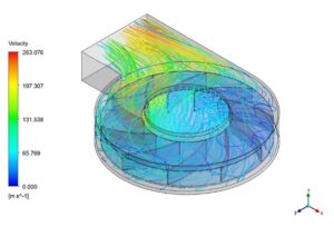
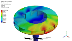
Figure 1: Fluid-Structure Interaction example: The fluid flow pushing the pump blades causes the pump to move.
Basics of Fluid-Solid Interaction
Fluid-Solid Interaction and Fluid-Structure Interaction are two names for the same idea. They both mean the study of how fluids and solid parts work together. In this interaction, the fluid pushes on the solid, and the solid can change shape or move. This change can also affect the fluid flow. Understanding this two-way effect is very important in many engineering problems. There are two main types of fluid solid interaction simulation: one-way and two-way. In one-way fluid-structure interaction, the fluid affects the solid, but the solid does not change the fluid flow. This is simpler and faster to calculate. In two-way fluid-structure interaction, both the fluid and the solid affect each other. This type is more accurate but needs more computing power.
When engineers work on fluid-structure interaction, they use special software. One common software is ANSYS. The fluid solid interaction ANSYS tools allow users to simulate both the fluid and the solid parts together. Another software is COMSOL, which also offers fluid solid interaction simulation. The study of fluid structure interaction helps engineers solve many problems. For example, it is used to check if a bridge can handle wind forces or if a pump’s parts can survive pressure from flowing liquid. Many engineers learn about this in a fluid structure interaction course or use tutorials to improve their skills.
In summary, fluid solid interaction and fluid-structure interaction show how fluids and solids work together. Using software like ANSYS or COMSOL, engineers can simulate this interaction and design safer, better machines and structures.
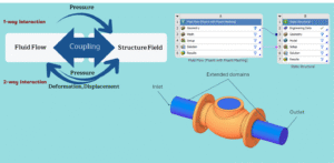
Figure 2: One-way vs. two-way fluid-structure interaction: one-way affects only the solid, two-way affects both fluid and solid.
Numerical Simulation of Fluid-Structure Interaction
Numerical simulation is a way to study fluid-structure interaction using computers. It helps engineers see how fluids and solids behave together without building physical models. This saves time and money and allows testing many designs quickly. In fluid-structure interaction numerical simulation, two main parts work together: fluid flow and solid structure. Engineers use computational fluid dynamics (CFD) to study the fluid part. They use structural analysis to study the solid part. Then, these two parts are connected, or coupled, in the simulation.
There are different methods to connect fluid and solid parts in simulation. One method is called strongly coupled fluid-structure interaction. This means the fluid and solid parts are solved together many times during the simulation. It gives very accurate results but needs more computer power. Another method is called loosely coupled. Here, fluid and solid parts are solved separately and shared less often. This method is faster but less accurate.
Modern software supports these methods. ANSYS is a popular choice for fluid structure interaction simulation. It can handle both CFD and structural parts and connect them for accurate results. Other software like COMSOL also offers fluid solid interaction simulation with multiphysics capabilities.
Using numerical simulation for FSI helps engineers design better machines, buildings, and devices. It is important in fields like aerospace, automotive, and biomedical engineering.
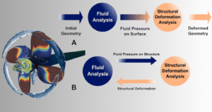
Figure 3: Numerical simulation of fluid-structure interaction shows how fluid flow and solid deformation are connected.
FSI in ANSYS Software
Fluid solid interaction ANSYS tools are very powerful for solving fluid-structure interaction problems. ANSYS software helps engineers simulate how fluids and solids work together. The software can connect fluid flow and solid parts in one environment. This makes it easier to study and design complex systems.
ANSYS Workbench is a popular platform for fluid structure interaction. It combines different solvers for fluid and solid parts. For fluids, ANSYS uses tools like Fluent and CFX. For solid parts, it uses ANSYS Mechanical. These tools work together to perform fluid structure interaction simulation. ANSYS supports both one-way and two-way coupling. This means you can choose simple or detailed models based on your needs. The software also supports strongly coupled fluid-structure interaction for very accurate results. Using ANSYS for FSI helps engineers solve many real problems. For example, they can study how air pushes on airplane wings or how water affects a pump’s parts. The fluid solid interaction simulation in ANSYS is trusted in many industries because it is accurate and reliable.
If you want to learn more, many fluid structure interaction courses include ANSYS training. These courses help users understand how to use ANSYS for FSI problems.
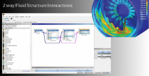
Figure 4: ANSYS Workbench interface showing fluid-structure interaction setup with Fluent and Mechanical solvers.
Understanding Fluid-Solid Coupling
Fluid-solid coupling is a key part of fluid-structure interaction. This process connects fluid flow and solid deformation, allowing engineers to study how forces and motion interact between them. In simulations, data is exchanged between fluid and solid models repeatedly to ensure accuracy. This is called iterative coupling. It helps capture the full interaction of forces, displacements, and pressures in real-world applications.
However, setting up proper coupling can be challenging. Engineers must carefully define the properties of both fluid and solid domains and ensure smooth data transfer. Using tools like ANSYS Workbench, the coupling process becomes easier and more reliable. These tools automatically exchange data between fluid and solid solvers during each step of the simulation.
By understanding fluid-solid coupling, engineers can improve simulation accuracy and study complex systems like bridges, pumps, and airplane wings. This coupling is essential for solving real-world problems where fluid and solid parts interact dynamically.
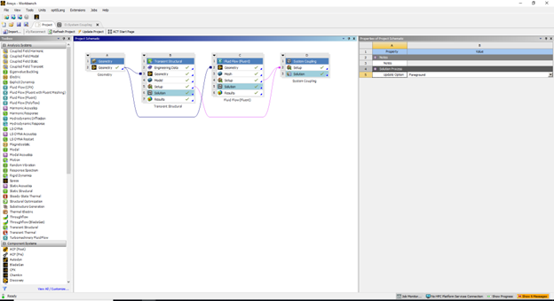
Figure 5: Fluid-solid coupling, Iterative data transfer ensuring accurate results in transient structural and fluid flow simulations.
Defining the Fluid-Solid Interface in Mechanical Environments
The fluid-solid interface is the key area where the fluid and solid domains interact in a simulation. This interface acts as the communication point for forces, pressures, and displacements between the two domains. Properly defining the fluid-solid interface in ANSYS is essential for accurate results in fluid-structure interaction modeling.
In the ANSYS Mechanical environment, engineers use the “Fluid Solid Interface” tool to set up this coupling. This tool allows the user to specify the regions where the fluid and solid interact, ensuring the correct transfer of data like forces from the fluid side and displacements from the solid side. Without this step, the simulation cannot capture the true behavior of the system under study.
The image shows how to define the fluid-solid interface in ANSYS Mechanical. Engineers can select the interface region and configure properties like temperature, pressure, or force conditions. This step is critical for fluid structure interaction analysis, as it connects the physical mechanics of both domains. Proper setup of the interface ensures the simulation runs smoothly and produces reliable results.
By defining the interface carefully, engineers can study complex systems such as bridges under wind loads or pumps where fluid flow interacts with moving components. Accurate definition of this interaction is essential for solving real-world engineering challenges.
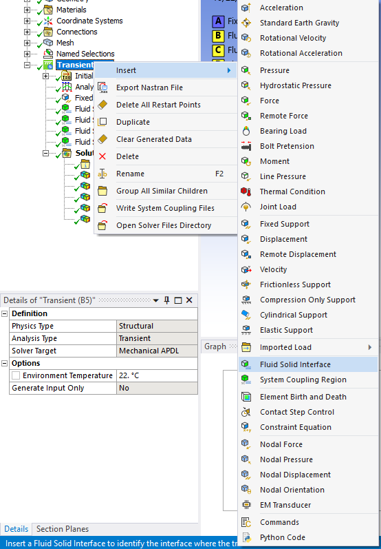
Figure 6: Defining fluid-solid interfaces in ANSYS ensures proper force and motion transfer between fluid and structural environments.
Coupling Systems in ANSYS Fluent
Fluid-solid coupling systems are essential for solving fluid-structure interaction simulations. In ANSYS Fluent, coupling systems connect fluid and solid domains, allowing them to interact dynamically during simulations. This image shows the dynamic mesh zones used in ANSYS Fluent to manage the motion of solid boundaries interacting with fluid flow. These mesh zones are critical for ensuring smooth data transfer between fluid and solid systems during the coupling process.
The System Coupling option in Fluent is used to define how fluid and solid domains exchange information. Engineers can specify different types of motion for mesh zones, such as deforming or stationary, depending on the physical behavior of the system. For example, in a pump simulation, the rotating blades (solid domain) deform the fluid flow, and Fluent dynamically adjusts the mesh to account for this interaction.
By using dynamic mesh zones and system coupling, engineers can simulate real-world systems where fluid and solid components interact in complex ways. This process ensures accurate results for applications such as turbine design, biomedical devices, or structural systems subjected to fluid forces. Fluent’s fluid solid interaction analysis tools provide flexibility and precision in defining coupling systems, saving time and improving the reliability of simulations.
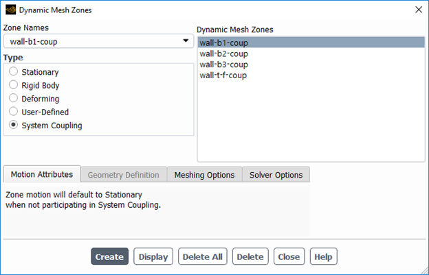
Figure 7: The system coupling setup in ANSYS Workbench simplifies fluid-solid interaction simulation with dynamic meshing capabilities.
Fluid-Solid Coupling Data Exchange: Iterative Process
The Figure 9 illustrates the iterative process of fluid-solid coupling in simulations. It displays the data transfer between fluid flow (Fluent) and transient structural components, emphasizing how the two domains interact dynamically. This diagram represents the changes in Root Mean Square (RMS) values during multiple coupling iterations, ensuring the simulation achieves convergence and stability.
In fluid-structure interaction modeling, the coupling process is crucial for transferring forces, displacements, and pressures between the fluid and solid systems. The red curve represents the data transfer from the fluid flow domain, while the green curve represents the data from the transient structural domain. The fluctuations visible in the graph reflect how the system adjusts during each iteration to balance the interaction forces and achieve accurate results.
The iterative nature of fluid-solid coupling ensures that the simulation captures the real-world dynamics of complex systems, such as the behavior of a bridge under wind loads or a pump operating with fluid flow. Engineers rely on tools like ANSYS Fluent coupling systems to configure this interaction effectively. By monitoring the RMS values in the coupling diagram, they can evaluate the performance of their simulation and make necessary adjustments to achieve accurate outcomes.
Understanding this diagram is vital for fluid structure interaction analysis, as it demonstrates the importance of maintaining a stable, two-way data exchange between fluid and solid domains. Without proper coupling, the simulation may fail to capture the true physical behavior of the system, resulting in unreliable results.
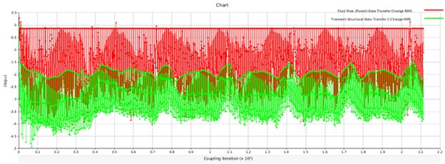
Figure 9: The coupling diagram shows iterative data exchange between fluid flow (red) and transient structural domains (green) for achieving convergence

5
Bollards and roadside elements are continuously subjected to unsteady aerodynamic forces, especially in open urban environments or highways.
2. Thermal Analysis of Lighting Columns & Electrical Systems
Lighting columns are exposed to combined thermal loads from:
Solar radiation
Electrical heat generation (LED drivers, circuits)
Ambient temperature fluctuations
Limited natural convection
What We Evaluate:
Temperature distribution along the column
Heat accumulation in enclosed components
Cooling efficiency due to airflow
Thermal gradients affecting material integrity
Risk of overheating or failure
Thermal Modeling Includes:
Convection (forced & natural)
Radiation (solar + surface emission)
Conduction through materials
Coupled CFD–thermal simulation
3. Urban Wind Flow & Environmental Interaction
Road infrastructure exists within complex urban flow environments where airflow is influenced by buildings, traffic, and terrain.
Simulation Capabilities:
Wind flow around streets and intersections
Turbulence modeling in urban environments
Wake formation behind structures
Pedestrian-level wind comfort analysis
Pollutant dispersion (optional extension)
Core Engineering Equations & Physical Models

Industrial Applications
Smart city infrastructure
Highway safety systems
Urban lighting networks
Outdoor electrical enclosures
Roadside barriers and bollards
Environmental impact assessment
Engineering Value & Benefits

epsilonX Expertise in Aerodynamics and Aerospace CFD Simulation Using ANSYS Fluent
At epsilonX, we specialize in delivering high-quality solutions in aerodynamics and aerospace CFD simulation using industry-leading tools, ANSYS Fluent aerodynamics software. Our team is highly experienced in conducting aerodynamic CFD simulations and analysis, advanced modeling of compressible and turbulent flows, and CFD of external aerodynamics and turbomachinery. Whether you’re looking for an ANSYS Fluent aerodynamics tutorial, a complete CFD analysis in aerodynamics, or need assistance with your aerospace CFD projects, we’ve got you covered.
You can explore our portfolio of completed aerodynamics CFD software projects at the top of this page or browse through our ready-made simulations in the CFD SHOP.