Aeroacoustic CFD Analysis of a NACA 4-(3)(08)-03 Propeller Using ANSYS Fluent
28 min read
Aeroacoustic CFD Analysis of a NACA 4-(3)(08)-03 Propeller Using ANSYS Fluent and Ffowcs Williams–Hawkings Acoustic Modeling

Introduction
As the aerospace industry continues its transition toward electric propulsion systems, aeroacoustic performance has become just as important as aerodynamic efficiency. Whether designing unmanned aerial vehicles (UAVs), electric Vertical Take-Off and Landing (eVTOL) aircraft, or advanced drone propulsion systems, engineers must now optimize both thrust generation and noise reduction. Communities, regulatory agencies, and commercial operators increasingly demand quieter aircraft capable of operating safely within urban environments without creating excessive environmental noise.
Propellers are among the dominant sources of aircraft noise. As blades rotate through the air, they generate highly complex pressure fluctuations, turbulent wake structures, and vortex interactions that radiate sound into the surrounding environment. These acoustic emissions are commonly divided into tonal noise, which occurs at blade-passing frequencies, and broadband noise, which results from turbulent flow structures interacting with blade surfaces and trailing edges. Understanding these mechanisms is essential for designing quieter propulsion systems without compromising aerodynamic performance.
At Epsilon X Sky, Computational Fluid Dynamics (CFD) combined with aeroacoustic modeling provides engineers with powerful tools for predicting propeller noise before physical prototypes are manufactured. Using ANSYS Fluent for aerodynamic simulation and the Ffowcs Williams–Hawkings (FW-H) Acoustic Model for far-field noise prediction, our engineering team evaluates both aerodynamic efficiency and acoustic behavior simultaneously. This integrated simulation approach significantly reduces development costs while accelerating product optimization through virtual engineering.
The NACA 4-(3)(08)-03 propeller represents an excellent case study because its aerodynamic characteristics allow engineers to investigate the interaction between blade geometry, airflow, vortex formation, pressure fluctuations, and acoustic emissions. By carefully analyzing these physical phenomena, designers can identify opportunities to reduce noise while maintaining or even improving thrust and overall efficiency.
Unlike traditional aerodynamic analysis, aeroacoustic simulation requires significantly greater attention to transient flow behavior, mesh quality, turbulence modeling, numerical accuracy, and acoustic post-processing. Even small numerical inaccuracies within the aerodynamic solution can produce significant errors in the predicted acoustic response. Consequently, aeroacoustic CFD demands a carefully structured engineering workflow supported by rigorous validation and high-fidelity numerical methods.
This article explores how Epsilon X Sky performs aeroacoustic analysis of the NACA 4-(3)(08)-03 propeller using ANSYS Fluent and the Ffowcs Williams–Hawkings acoustic model, highlighting engineering best practices for geometry preparation, mesh generation, transient CFD simulation, acoustic prediction, validation, and design optimization.
Fundamentals of Aeroacoustics and the NACA 4-(3)(08)-03 Propeller

Modern aerospace engineering no longer evaluates propulsion systems solely on the basis of thrust and efficiency. Noise has become a major design constraint, particularly for electric aircraft intended to operate close to populated areas. Every rotating propeller generates sound through the interaction of aerodynamic forces with the surrounding air, and accurately predicting these sound sources is one of the most challenging problems in computational engineering.
Unlike jet engines, where combustion contributes significantly to overall noise generation, electric propulsion systems are dominated by aerodynamic noise. As each propeller blade rotates, it continuously accelerates and decelerates surrounding air, producing pressure waves that propagate away from the aircraft. These pressure fluctuations combine with turbulent wake structures and vortex shedding to create complex acoustic fields that vary with operating conditions, blade geometry, rotational speed, and atmospheric conditions.
The NACA 4-(3)(08)-03 propeller provides an ideal platform for investigating these aeroacoustic mechanisms because its blade profile exhibits well-defined aerodynamic characteristics while remaining representative of many practical aerospace applications. The blade geometry influences airflow acceleration, boundary-layer development, pressure distribution, and tip vortex formation, all of which contribute directly to the acoustic signature of the propeller.
One of the primary sources of propeller noise is loading noise, which originates from the unsteady aerodynamic forces acting on the rotating blades. As the blades continuously generate lift and thrust, pressure differences develop between the suction and pressure sides of each airfoil section. These pressure variations radiate acoustic energy into the surrounding atmosphere, producing tonal noise components that occur at blade-passing frequencies and their harmonics.
A second major contributor is thickness noise, generated simply by the physical displacement of air as the rotating blades move through space. Although often smaller than loading noise for highly efficient propellers, thickness noise remains an important component of the overall acoustic spectrum and must be included in comprehensive aeroacoustic analyses.
Broadband noise arises from turbulent flow structures interacting with blade surfaces. As airflow passes over the airfoil, turbulent eddies develop within the boundary layer and eventually interact with the trailing edge. This interaction produces randomly distributed pressure fluctuations across a wide range of frequencies. Unlike tonal noise, broadband noise lacks distinct frequency peaks but contributes significantly to the perceived loudness of the propeller.
Blade-tip vortices represent another critical aeroacoustic phenomenon. As pressure equalizes around the blade tip, concentrated vortical structures form and persist within the wake downstream of the propeller. These vortices interact with neighboring blades, support structures, and downstream aerodynamic surfaces, generating additional pressure fluctuations and acoustic emissions. Properly capturing blade-tip vortices is essential for accurate aeroacoustic prediction.
Rotor wake development further complicates the flow field. Multiple vortices merge, stretch, and dissipate as they convect downstream, creating highly transient turbulent structures. These wake interactions influence both aerodynamic efficiency and acoustic behavior, making transient CFD simulations essential for understanding real operating conditions.
Operating conditions strongly influence noise generation. Increasing rotational speed generally increases thrust but also raises blade-tip velocity, intensifies pressure gradients, and amplifies vortex strength, leading to higher acoustic emissions. Blade pitch angle, inflow velocity, air density, and angle of attack also affect both aerodynamic performance and noise generation. Engineers must therefore evaluate multiple operating conditions rather than relying on a single simulation point.
At Epsilon X Sky, aeroacoustic studies begin by defining clear engineering objectives that extend beyond simple noise measurement. Our engineers seek to identify where noise originates, understand why it is generated, determine how it propagates, and evaluate how blade geometry or operating conditions can reduce acoustic emissions while preserving aerodynamic efficiency. This systematic approach transforms aeroacoustic simulation from a post-processing exercise into a powerful design optimization tool.
Understanding the physical mechanisms responsible for propeller noise is the foundation upon which accurate aeroacoustic simulation and effective engineering optimization are built.
Geometry Preparation, Mesh Generation, and CFD Setup in ANSYS Fluent

Accurate aeroacoustic prediction begins long before the acoustic model is activated. The quality of the final noise prediction depends primarily on the accuracy of the underlying aerodynamic simulation. Since the Ffowcs Williams–Hawkings (FW-H) acoustic model derives its sound sources directly from the transient pressure field computed by the CFD solver, any numerical errors introduced during geometry preparation, mesh generation, or solver configuration will propagate into the acoustic solution. At Epsilon X Sky, considerable engineering effort is invested in creating a robust CFD model before any acoustic calculations are performed.
The first step involves preparing the propeller geometry for simulation. CAD models generated for manufacturing typically contain numerous small features, including fasteners, tiny fillets, embossed markings, bolt holes, and assembly details that have negligible influence on the external flow field. While these details are essential for production, they unnecessarily increase computational cost and complicate mesh generation. Therefore, simulation geometry is carefully simplified while preserving every aerodynamic surface responsible for lift generation, pressure distribution, and vortex formation.
A simulation model should accurately represent the physics of the problem rather than every manufacturing detail contained in the original CAD assembly.
Particular attention is paid to the blade profile. The leading edge, trailing edge, blade twist, thickness distribution, tip geometry, and hub transition are all maintained with high geometric accuracy because these features strongly influence aerodynamic loading and acoustic generation. Even slight distortions in blade shape can alter pressure fluctuations and change the predicted sound pressure levels.
Once the geometry has been prepared, the computational domain is established. Since the propeller continuously accelerates air as it rotates, the surrounding flow field extends far beyond the blade tips. The inlet, outlet, side, and far-field boundaries are positioned sufficiently far from the rotating propeller to prevent artificial reflections and boundary interference. If the computational domain is too small, pressure waves generated by the propeller may interact with the boundaries, introducing numerical errors that compromise both aerodynamic and acoustic accuracy.
The rotating propeller itself requires special numerical treatment. In ANSYS Fluent, several methods are available depending on the engineering objective. For highly accurate aeroacoustic prediction, Sliding Mesh techniques are often preferred because they physically rotate the computational mesh during the transient simulation. Unlike steady Moving Reference Frame (MRF) methods, sliding mesh captures the actual blade motion and accurately reproduces the periodic pressure fluctuations responsible for tonal noise generation.
For preliminary aerodynamic studies where computational efficiency is prioritized, MRF may still provide valuable engineering insight. However, because aeroacoustic analysis depends on resolving time-dependent pressure variations, transient sliding mesh simulations generally produce significantly more accurate acoustic predictions.
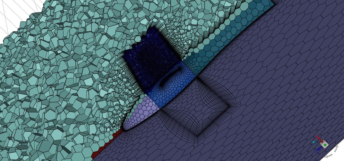
Mesh generation represents one of the most critical stages of the entire workflow. The computational mesh divides the surrounding airflow into millions of control volumes where the governing fluid equations are solved numerically. Poor mesh quality inevitably produces inaccurate pressure fields, weak vortex structures, excessive numerical diffusion, and unreliable acoustic predictions.
At Epsilon X Sky, hybrid mesh strategies are commonly employed for rotating propeller simulations. Inflation layers consisting of multiple prism elements are generated along the blade surfaces to accurately resolve the boundary layer. These layers capture steep velocity gradients near the wall and provide accurate predictions of skin friction, wall pressure, and flow separation. Proper boundary-layer resolution is particularly important because pressure fluctuations along the blade surface directly influence loading noise.

Outside the near-wall region, polyhedral or tetrahedral cells efficiently capture the three-dimensional flow surrounding the rotating blades. Local mesh refinement is applied around the blade tips, hub region, and wake development zones where strong vortices and turbulent structures form. Blade-tip vortices are among the dominant contributors to propeller noise and therefore require particularly fine spatial resolution.
Wake refinement continues several propeller diameters downstream to preserve the integrity of the helical vortex system generated by blade rotation. If this region is insufficiently refined, numerical diffusion rapidly dissipates the vortices, reducing both aerodynamic accuracy and acoustic fidelity. At Epsilon X Sky, adaptive refinement techniques are frequently employed to concentrate computational resources only where they provide meaningful improvements in solution quality.
Mesh quality is continuously evaluated throughout generation. Engineers examine skewness, orthogonality, aspect ratio, element growth rate, and cell transition smoothness to minimize numerical instability. High-quality elements improve solver convergence while reducing interpolation errors that could contaminate the transient pressure signals used by the acoustic solver.
Following mesh generation, engineers configure the governing physical models within ANSYS Fluent. Since propeller aeroacoustics involves unsteady vortex formation and pressure fluctuations, transient simulations are mandatory. Time-step selection becomes particularly important because insufficient temporal resolution can fail to capture blade-passing frequencies and higher harmonic components of the acoustic spectrum.
The turbulence model must also be selected carefully. The k-ω SST turbulence model remains one of the most widely used approaches because it provides excellent predictions of adverse pressure gradients, flow separation, and near-wall behavior while maintaining reasonable computational cost. For higher-fidelity studies involving detailed vortex dynamics and broadband noise prediction, more advanced methods such as Detached Eddy Simulation (DES) or Large Eddy Simulation (LES) may be employed. Although these techniques require substantially greater computational resources, they resolve a larger portion of the turbulent flow field and significantly improve aeroacoustic accuracy.
Boundary conditions are established to represent realistic operating conditions. Engineers define rotational speed, inlet velocity, atmospheric pressure, temperature, and turbulence intensity according to the intended flight condition. Multiple operating points are typically analyzed because propeller noise varies significantly with rotational speed, inflow velocity, blade loading, and angle of attack.
Convergence monitoring extends beyond residual reduction. During every transient simulation, engineers continuously monitor thrust, torque, lift, drag, pressure coefficients, and blade loading to ensure that the aerodynamic solution remains physically consistent. Pressure histories are recorded at numerous monitoring locations because these time-dependent pressure signals later serve as direct inputs to the FW-H acoustic model.
Validation remains an integral component of the CFD workflow. Mesh independence studies verify that aerodynamic coefficients remain stable as mesh density increases, while time-step independence analyses ensure that transient pressure fluctuations are accurately resolved. Only after both spatial and temporal independence have been confirmed can engineers proceed confidently to aeroacoustic prediction.
At Epsilon X Sky, every aerodynamic simulation undergoes multiple engineering reviews before acoustic post-processing begins. Solver settings, mesh quality, turbulence modeling, rotating mesh configuration, and convergence behavior are systematically verified to ensure that the transient flow field accurately represents the physical behavior of the rotating propeller.
High-quality aeroacoustic prediction is built upon an equally high-quality aerodynamic simulation. Without accurate CFD, reliable acoustic analysis is simply impossible.
Ffowcs Williams–Hawkings (FW-H) Acoustic Modeling and Aeroacoustic Prediction

Once the transient aerodynamic simulation has reached a stable and physically consistent solution, the next stage of the engineering workflow involves predicting the sound radiated by the rotating propeller. While Computational Fluid Dynamics accurately describes the flow field surrounding the blades, it does not directly provide the sound that propagates into the surrounding environment. To bridge this gap, aeroacoustic engineers employ specialized acoustic analogies capable of transforming unsteady aerodynamic data into far-field noise predictions. Among these methods, the Ffowcs Williams–Hawkings (FW-H) acoustic model has become the industry standard for aerospace aeroacoustic analysis.
Originally developed as an extension of Lighthill's Acoustic Analogy, the FW-H equation incorporates moving solid boundaries, making it particularly suitable for rotating propellers, helicopter rotors, UAV propulsion systems, wind turbines, and eVTOL aircraft. Unlike conventional CFD, which solves airflow behavior directly, the FW-H model computes how fluctuating aerodynamic forces generate pressure waves that travel through the atmosphere and are perceived as sound by an observer.
At Epsilon X Sky, the FW-H model is integrated with ANSYS Fluent to predict propeller noise using pressure and velocity data obtained from high-fidelity transient CFD simulations. This approach enables engineers to evaluate acoustic performance long before manufacturing a physical prototype, significantly reducing development costs and shortening design cycles.
The accuracy of the FW-H method depends heavily on the quality of the transient CFD solution. Since acoustic pressure levels are several orders of magnitude smaller than aerodynamic pressure variations, even minor numerical errors in the flow solution can produce significant inaccuracies in the predicted sound field. Consequently, transient pressure fluctuations must be captured with exceptional numerical precision throughout the simulation.
The first step in implementing the FW-H model involves selecting an appropriate acoustic integration surface. This virtual surface encloses the rotating propeller and serves as the boundary across which aerodynamic pressure fluctuations are monitored. Choosing the correct integration surface is crucial because it determines which flow structures contribute to the acoustic calculation. If the surface is positioned too close to the blades, important vortex structures may be excluded. Conversely, if it is placed too far away, numerical dissipation may weaken the pressure signals before they reach the integration boundary.
At Epsilon X Sky, integration surfaces are carefully designed to fully encompass the rotating propeller, blade-tip vortices, and near-field pressure fluctuations while maintaining sufficient distance from the computational boundaries. This configuration ensures that all significant acoustic sources are included within the FW-H calculation without introducing unnecessary numerical complexity.
One of the major advantages of the FW-H method is its ability to separate different physical noise generation mechanisms. Engineers typically distinguish between loading noise, thickness noise, and quadrupole noise, each originating from different aerodynamic phenomena.
Loading noise results from the unsteady aerodynamic forces acting on the rotating blades. As lift and thrust vary during blade rotation, fluctuating pressure distributions generate sound waves that propagate into the surrounding air. This mechanism is generally responsible for the dominant tonal peaks observed in propeller noise spectra.
Thickness noise originates from the displacement of air caused by the rotating blade volume itself. As each blade moves through space, it physically pushes surrounding air outward, generating pressure disturbances even in the absence of aerodynamic loading. Although thickness noise is often smaller than loading noise for modern propellers, it remains an important contributor to the overall acoustic signature.
Quadrupole noise arises from turbulent flow structures within the fluid itself. High-speed turbulent eddies continuously generate pressure fluctuations that radiate sound independently of the blade surfaces. While quadrupole noise becomes dominant in high-speed jet flows, loading and thickness noise usually represent the primary acoustic sources for low-Mach-number electric propellers.
The transient CFD simulation continuously records pressure histories throughout the rotating cycle. These pressure signals serve as the input for the FW-H solver, which transforms the aerodynamic data into acoustic pressure histories measured at specified observer locations. Engineers can position virtual microphones around the aircraft to evaluate how noise propagates in different directions and determine which regions experience the highest sound pressure levels.
Observer placement plays an important role in aeroacoustic analysis. Virtual microphones may be positioned above, below, in front of, or behind the propeller depending on the engineering objectives. For eVTOL aircraft, engineers often investigate noise experienced by passengers, nearby pedestrians, surrounding buildings, and ground observers during take-off and landing operations.
The FW-H model produces time-dependent acoustic pressure signals that can be analyzed using Fast Fourier Transform (FFT) techniques to obtain frequency-domain information. These frequency spectra reveal the characteristic tonal peaks associated with blade-passing frequency as well as higher harmonic components generated by periodic blade motion.

The Blade Passing Frequency (BPF) represents one of the most important quantities in propeller aeroacoustics. It corresponds to the frequency at which blades pass a stationary observer and typically dominates the acoustic spectrum. Additional harmonic peaks occur at integer multiples of the BPF, providing valuable insight into rotor dynamics, aerodynamic loading, and overall acoustic behavior.
Beyond tonal components, engineers also evaluate broadband noise generated by turbulent flow interactions. Broadband noise appears as a continuous distribution of acoustic energy across a wide range of frequencies rather than distinct spectral peaks. Although more difficult to predict than tonal noise, broadband noise significantly influences the perceived loudness of electric propulsion systems and often becomes a primary target during optimization studies.
Visualization tools further enhance engineering understanding of the acoustic field. Engineers generate directivity plots illustrating how sound propagates in different directions around the propeller. These visualizations reveal whether acoustic energy is concentrated beneath the aircraft, behind the propeller disk, or distributed uniformly throughout the surrounding environment. Such information is essential when designing quieter propulsion systems for urban air mobility applications.
Sound Pressure Level (SPL) contours provide another valuable engineering output. These contour maps identify regions experiencing the highest acoustic intensity and help engineers correlate noise generation with specific aerodynamic features such as blade tips, trailing edges, or hub vortices. By linking acoustic emissions directly to flow structures, engineers can identify the physical origins of noise rather than merely measuring its magnitude.
Validation remains a critical component of every aeroacoustic study. Whenever possible, predicted acoustic spectra are compared with experimental microphone measurements or published benchmark data. Agreement between numerical and experimental results increases confidence in both the aerodynamic simulation and the acoustic modeling methodology.
At Epsilon X Sky, aeroacoustic analysis extends beyond predicting noise levels. Our engineering team interprets acoustic results alongside aerodynamic performance metrics to identify practical design improvements. Blade geometry modifications, rotational speed adjustments, optimized blade spacing, refined tip profiles, and altered operating conditions are evaluated to reduce acoustic emissions while preserving thrust and efficiency.
Accurate aeroacoustic simulation transforms noise prediction from a costly experimental process into a powerful virtual engineering capability, enabling quieter and more efficient propulsion systems to be developed long before physical testing begins.
Through the integration of ANSYS Fluent with the Ffowcs Williams–Hawkings acoustic model, Epsilon X Sky delivers comprehensive aeroacoustic solutions that combine aerodynamic excellence with acoustic optimization, supporting the development of next-generation UAVs, eVTOL aircraft, drones, and advanced aerospace propulsion systems.
Simulation Results, Noise Source Analysis, and Engineering Optimization
After completing the transient aerodynamic simulation and processing the acoustic solution using the Ffowcs Williams–Hawkings (FW-H) model, engineers begin one of the most valuable stages of the entire workflow: interpreting the results. While obtaining aerodynamic and acoustic data is an important milestone, the true engineering value lies in understanding the physical mechanisms responsible for noise generation and using that knowledge to improve the propeller design. At Epsilon X Sky, simulation results are transformed into practical engineering recommendations that guide the optimization of both aerodynamic performance and acoustic efficiency.
The first step involves examining the overall aerodynamic performance of the NACA 4-(3)(08)-03 propeller. Engineers evaluate thrust, torque, power consumption, efficiency, lift distribution, pressure coefficients, and velocity fields throughout the computational domain. These parameters establish whether the propeller meets its performance objectives before any acoustic improvements are considered. A quieter propeller should never sacrifice the aerodynamic performance required by the mission.

Pressure contour plots reveal the distribution of aerodynamic loading across the blade surfaces. Strong pressure differences between the suction and pressure sides generate the lift required for propulsion, but they also contribute directly to loading noise. Regions of extremely high pressure gradients often correspond to areas where acoustic energy is generated most intensely. By identifying these regions, engineers can determine which portions of the blade geometry have the greatest influence on the overall sound signature.
Velocity contour visualization provides additional insight into the airflow surrounding the rotating propeller. High-speed flow acceleration occurs along the blade surfaces, while complex wake structures develop downstream. Engineers carefully examine these velocity distributions to detect regions of flow separation, recirculation, and wake interaction. Any instability within the wake can amplify turbulent fluctuations and increase broadband noise generation.
One of the most important visualizations involves blade-tip vortices. As pressure equalizes around the blade tips, concentrated vortical structures form and spiral downstream in a helical pattern. These vortices remain coherent over long distances and represent one of the dominant aerodynamic features responsible for propeller noise. Strong blade-tip vortices not only reduce propulsive efficiency but also generate significant acoustic emissions through unsteady pressure fluctuations. Minimizing tip vortex strength is often one of the most effective strategies for reducing overall propeller noise.
Streamline analysis helps engineers understand how air flows through and around the rotating propeller. Smooth, attached streamlines generally indicate efficient aerodynamic performance, whereas irregular or highly turbulent flow patterns may suggest opportunities for blade optimization. Engineers frequently compare streamline patterns across multiple operating conditions to identify changes in flow behavior as rotational speed or inflow velocity varies.
The transient pressure histories obtained during the CFD simulation are then transformed into acoustic signals by the FW-H solver. These signals are analyzed using Fast Fourier Transform (FFT) techniques to generate frequency spectra. One of the first quantities examined is the Blade Passing Frequency (BPF), which appears as the dominant tonal peak within the acoustic spectrum. Additional harmonics occur at multiples of the BPF and provide valuable information about blade loading, rotational dynamics, and periodic aerodynamic behavior.
While tonal noise is often the most recognizable component of propeller acoustics, engineers also evaluate broadband noise levels. Broadband noise results from turbulent eddies interacting with the blade surfaces and trailing edges, producing acoustic energy across a wide range of frequencies. In electric propulsion systems, broadband noise frequently dominates the perceived loudness, especially at lower rotational speeds. Consequently, reducing turbulent flow structures becomes an important objective during design optimization.
Sound Pressure Level (SPL) distributions are calculated at multiple observer locations surrounding the propeller. Virtual microphones positioned ahead of, behind, above, and below the rotor capture how acoustic energy propagates through the environment. These observer locations allow engineers to evaluate directional noise characteristics and identify regions where sound exposure may exceed regulatory limits.
Directivity plots provide another valuable engineering tool. Rather than measuring sound intensity at a single location, directivity diagrams illustrate how acoustic energy radiates in different directions. Certain propeller geometries concentrate sound beneath the aircraft, while others distribute acoustic energy more uniformly. Understanding these radiation patterns helps engineers optimize blade geometry for specific operating environments, particularly in urban air mobility applications where community noise is a major concern.
At Epsilon X Sky, aerodynamic and acoustic data are always evaluated together rather than independently. Engineers examine whether regions producing the highest aerodynamic loading also correspond to the strongest acoustic sources. This integrated analysis enables targeted design improvements that reduce noise without unnecessarily compromising thrust or efficiency.
Blade geometry optimization represents one of the most effective methods for reducing aeroacoustic emissions. Small modifications to blade twist distribution, airfoil camber, chord length, trailing-edge thickness, or tip shape can significantly alter both aerodynamic performance and acoustic behavior. Rounded or swept blade tips, for example, often reduce vortex intensity while maintaining efficient thrust generation. Likewise, optimizing the trailing-edge geometry can decrease turbulent pressure fluctuations and lower broadband noise levels.
Rotational speed optimization also plays an important role. Increasing rotational speed generally increases thrust, but it also raises blade-tip velocity and amplifies pressure fluctuations. Engineers therefore evaluate multiple operating speeds to identify the optimal balance between propulsion performance and acoustic emissions. In many cases, slight reductions in rotational speed combined with improved blade geometry produce substantial noise reductions with minimal loss of thrust.
Parametric design studies further accelerate optimization. Using automated workflows integrated with ANSYS Fluent, engineers systematically vary blade parameters such as pitch angle, twist distribution, airfoil profile, hub dimensions, and rotational speed across numerous simulations. The resulting aerodynamic and acoustic performance data are compared to identify the configuration that provides the best overall balance between efficiency, structural integrity, and noise reduction.
Modern optimization algorithms can evaluate hundreds of design variations far more rapidly than traditional experimental methods. This capability allows engineers to explore a much larger design space while minimizing development costs and reducing reliance on physical prototyping. Simulation-driven optimization enables better engineering decisions long before manufacturing begins.
Validation remains essential throughout the optimization process. Improved numerical performance alone does not guarantee a better physical design. Whenever possible, optimized CFD and acoustic predictions are compared with wind tunnel measurements, microphone array data, or published experimental results to verify that the predicted improvements reflect real-world behavior.
At Epsilon X Sky, every optimization project concludes with a detailed engineering report that combines aerodynamic performance metrics, acoustic spectra, pressure distributions, velocity contours, streamline visualizations, vortex analysis, and engineering recommendations. Rather than presenting isolated numerical values, our reports explain the physical mechanisms responsible for the observed behavior and provide clear guidance for future design improvements.
The ultimate goal of aeroacoustic simulation is not simply to measure noise—it is to understand its origin and eliminate it through intelligent engineering design.
By integrating advanced CFD, transient aerodynamic analysis, FW-H acoustic prediction, and simulation-driven optimization, Epsilon X Sky helps aerospace manufacturers develop quieter, more efficient, and higher-performing propeller systems for UAVs, drones, eVTOL aircraft, and next-generation electric propulsion technologies.
Engineering Best Practices, Industrial Applications, Future Trends, and Conclusion
As electric propulsion technologies continue to reshape modern aviation, aeroacoustic engineering has evolved from a specialized research discipline into a fundamental component of aircraft development. Today's aerospace manufacturers must design propulsion systems that not only produce sufficient thrust and aerodynamic efficiency but also comply with increasingly strict environmental noise regulations. This challenge is particularly important for drones, unmanned aerial vehicles (UAVs), electric Vertical Take-Off and Landing (eVTOL) aircraft, and urban air mobility platforms, where operations occur close to residential and commercial areas. At Epsilon X Sky, we believe that aerodynamic performance and acoustic performance must be optimized together rather than treated as independent engineering objectives.
One of the most important engineering best practices is beginning every aeroacoustic project with clearly defined objectives. Before generating the computational mesh or selecting turbulence models, engineers must determine which performance parameters are most critical. Some projects prioritize thrust generation, while others focus on reducing blade-passing frequency noise, improving propeller efficiency, minimizing broadband turbulence noise, or optimizing performance during hover. Clearly defined engineering objectives ensure that computational resources are focused on solving meaningful design problems rather than simply generating numerical data.
Another essential best practice involves developing simulation-ready geometry rather than relying directly on manufacturing CAD models. Manufacturing assemblies often include numerous bolts, screws, brackets, embossed logos, cable supports, and small mechanical details that contribute little to external aerodynamic behavior. Retaining these features significantly increases mesh size and computational cost while offering little improvement in solution accuracy. At Epsilon X Sky, simulation geometry is carefully simplified to preserve only those surfaces that influence airflow, pressure distribution, vortex formation, and acoustic generation. This approach dramatically improves computational efficiency without sacrificing engineering reliability.
Mesh quality remains another cornerstone of successful aeroacoustic simulation. Increasing the number of computational cells alone does not guarantee more accurate predictions. High-quality elements with low skewness, smooth transition regions, and properly resolved boundary layers are far more important than simply generating extremely large meshes. Engineers carefully refine blade tips, trailing edges, wake regions, and areas of strong vortex interaction because these locations dominate both aerodynamic loading and acoustic emissions. A well-designed mesh produces stable numerical solutions and significantly improves the fidelity of both CFD and acoustic predictions.
Transient simulation is equally critical. Unlike steady aerodynamic analysis, aeroacoustic prediction depends on accurately resolving time-dependent pressure fluctuations generated by rotating blades. Selecting an appropriate time step ensures that blade-passing frequencies and higher harmonics are captured correctly without introducing numerical errors. Engineers must balance temporal resolution with computational efficiency to achieve accurate results within practical simulation times.
Validation represents one of the defining characteristics of professional engineering practice. Every simulation performed at Epsilon X Sky undergoes rigorous verification through convergence monitoring, mesh independence studies, time-step independence assessments, and comparison with published benchmark cases or experimental data whenever available. Simulation results should always be validated before they are used to support engineering decisions or product development.
The integration of aerodynamic and acoustic analysis provides one of the greatest advantages of modern simulation technology. Instead of evaluating thrust and noise separately, engineers can investigate how changes in blade geometry simultaneously influence aerodynamic efficiency and acoustic emissions. This multidisciplinary approach allows optimization algorithms to identify designs that maximize thrust while minimizing sound pressure levels. Such integrated engineering workflows are essential for the development of next-generation electric aircraft.
The industrial applications of aeroacoustic simulation continue to expand rapidly. In the UAV sector, quieter propellers improve surveillance capability, reduce environmental disturbance, and enhance operational flexibility. For commercial drones, lower noise levels increase public acceptance and facilitate regulatory approval for urban deliveries. In the eVTOL industry, aeroacoustic optimization has become a primary design requirement because excessive noise could limit the widespread adoption of urban air mobility systems. Wind turbine manufacturers also employ similar simulation techniques to reduce aerodynamic noise while maintaining high power generation efficiency.
Automotive cooling fans, industrial ventilation systems, HVAC equipment, marine propellers, and turbomachinery represent additional industries where aeroacoustic simulation delivers significant value. Although the physical applications differ, the underlying engineering principles remain remarkably similar. Rotating blades generate aerodynamic forces, turbulent wake structures, and pressure fluctuations that ultimately determine both efficiency and acoustic performance. The simulation methodologies developed for aerospace applications therefore provide valuable insights across numerous engineering disciplines.
Looking toward the future, the role of artificial intelligence and machine learning within aeroacoustic engineering is expected to grow substantially. AI-assisted optimization algorithms can evaluate thousands of blade geometries, identify optimal design trends, and accelerate engineering decision-making far beyond traditional trial-and-error methods. Rather than replacing engineers, these technologies enhance productivity by automating repetitive optimization tasks while allowing engineers to focus on interpreting results and developing innovative solutions.
Digital twin technology represents another major advancement. By combining CFD, structural analysis, sensor measurements, and real-time operational data, digital twins create continuously updated virtual representations of physical systems. Engineers can monitor propeller performance throughout its operational life, predict maintenance requirements, evaluate performance degradation, and refine future designs using real-world operating data. The integration of simulation with operational data will redefine how aerospace systems are designed, certified, and maintained in the coming decades.
Cloud-based high-performance computing (HPC) is also transforming simulation capabilities. Large transient aeroacoustic simulations that once required weeks of computation can now be completed in a fraction of the time using scalable cloud resources. This increased computational power enables engineers to employ advanced turbulence models such as Large Eddy Simulation (LES) and hybrid DES methods, providing unprecedented accuracy for broadband noise prediction and vortex-resolving simulations.
At Epsilon X Sky, we continuously invest in advanced ANSYS technologies, high-fidelity simulation methodologies, and engineering expertise to support the evolving needs of the aerospace industry. Our engineers combine Computational Fluid Dynamics, aeroacoustic modeling, structural analysis, thermal simulation, and optimization within a unified engineering workflow that delivers reliable, validated, and actionable results. Whether supporting drone manufacturers, aerospace research organizations, or advanced eVTOL developers, our objective remains the same: transforming innovative ideas into high-performance engineering solutions through simulation-driven design.
Simulation has become the foundation of modern aerospace innovation, enabling engineers to explore thousands of design possibilities virtually before manufacturing the first physical prototype.
As electric aviation continues to evolve, aeroacoustic engineering will play an increasingly important role in shaping the future of sustainable flight. Reducing noise without compromising efficiency is no longer simply an engineering challenge—it is a prerequisite for the successful integration of electric aircraft into everyday life. Through advanced CFD analysis, transient aerodynamic simulation, and the Ffowcs Williams–Hawkings acoustic model, Epsilon X Sky helps organizations develop quieter, more efficient, and environmentally responsible propulsion systems capable of meeting the demands of next-generation aerospace technologies.
Conclusion
The aeroacoustic analysis of the NACA 4-(3)(08)-03 propeller demonstrates how advanced simulation technologies can simultaneously improve aerodynamic efficiency and reduce acoustic emissions. By integrating ANSYS Fluent with the Ffowcs Williams–Hawkings (FW-H) acoustic model, engineers gain detailed insight into airflow behavior, vortex formation, pressure fluctuations, tonal noise, and broadband acoustic sources long before physical testing begins.
At Epsilon X Sky, we combine advanced CFD, aeroacoustic modeling, optimization, and engineering expertise to transform complex aerospace challenges into validated, data-driven solutions. Our multidisciplinary simulation approach enables clients to reduce development costs, accelerate product innovation, improve aerodynamic performance, and design quieter propulsion systems that meet the future demands of electric aviation.
The future of aerospace belongs to intelligent simulation—and Epsilon X Sky is committed to engineering that future through innovation, precision, and technical excellence.
Share this article