Hull Ventilation Analysis Using CFD: A Complete Engineering Guide
By Epsilon X Sky — Customized Ingenuity for a Smarter Life
Ventilation inside a ship's hull is one of those subjects that rarely gets the attention it deserves until something goes wrong. Engine rooms overheat, cargo holds accumulate moisture, crew quarters become uncomfortable, and in the worst cases, hazardous gases build up in confined spaces with nowhere to escape. Hull ventilation analysis using Computational Fluid Dynamics, or CFD, has become one of the most valuable tools available to naval architects and marine engineers for predicting these issues long before a vessel ever touches water. At Epsilon X Sky, we approach hull ventilation not as an afterthought bolted onto the design process, but as a core simulation discipline that informs everything from compartment layout to fan sizing and duct routing. This article walks through the full scope of hull ventilation CFD analysis, why it matters, how it is performed, and what makes the difference between a simulation that looks good on paper and one that actually predicts real-world airflow behavior.
The complexity of hull ventilation stems from the sheer variety of spaces that need to be considered together as one interconnected system. A modern vessel might include engine rooms generating enormous thermal loads, battery compartments on hybrid and electric ships requiring strict temperature control, cargo holds with their own humidity and gas concerns, and accommodation areas where human comfort is the priority. Each of these zones has different airflow requirements, different regulatory standards, and different failure consequences. CFD allows engineers to model all of these spaces simultaneously, capturing how air moves between compartments through doorways, grilles, ducting, and unintentional leakage paths, giving a realistic picture of the entire ventilation network rather than isolated pieces.
Beyond comfort and equipment protection, hull ventilation directly affects safety compliance and classification society approval. Standards from organizations such as IMO, DNV, ABS, and Lloyd's Register impose specific requirements on air exchange rates, temperature limits, and gas dispersion in enclosed spaces. CFD-based ventilation studies provide the quantitative evidence needed to demonstrate compliance, often replacing or supplementing physical testing that would otherwise require expensive mockups or full-scale trials. For shipyards and design firms, having a CFD partner capable of producing classification-ready ventilation reports can shorten approval cycles significantly and reduce the risk of costly redesigns discovered late in construction.

This guide is structured around four major pillars of hull ventilation CFD: understanding the engineering fundamentals that drive airflow inside a hull, setting up a CFD model correctly with the right geometry, mesh, and boundary conditions, interpreting the results in a way that leads to actionable design changes, and finally looking at how Epsilon X Sky delivers these projects from initial consultation through to final reporting. Whether you are a naval architect exploring CFD for the first time or an experienced engineer looking for a refresher on best practices, the sections below aim to give a thorough, practical overview of what hull ventilation analysis really involves and why it has become indispensable in modern marine design.
1. Engineering Fundamentals of Hull Ventilation and Airflow Behavior
Hull ventilation is fundamentally a problem of buoyancy-driven and forced convection acting together inside a geometrically complex, partially enclosed structure. Heat sources such as main engines, generators, exhaust manifolds, and electrical switchgear create localized thermal plumes that rise and interact with mechanical airflow supplied by fans and extracted through exhaust louvers. Understanding how these natural and forced flows combine is the starting point for any meaningful ventilation study, because a system that looks adequate based on simple flow-rate calculations can still fail if hot air becomes trapped in pockets that mechanical airflow never reaches.
One of the first concepts engineers must grasp is the difference between bulk ventilation rate and effective ventilation. A compartment might receive the theoretically correct number of air changes per hour according to a simple volumetric calculation, yet still have stagnant zones where temperatures climb well above acceptable limits. This happens because incoming air often takes the shortest path to the extraction point, short-circuiting the space and leaving corners, overhead areas near cable trays, or recesses behind machinery poorly served. CFD is uniquely suited to revealing these short-circuiting paths because it resolves the actual three-dimensional flow field rather than assuming uniform mixing.

Thermal stratification is another critical phenomenon in hull ventilation. Hot air naturally rises, and in tall compartments such as engine rooms this creates distinct temperature layers, with the upper deck levels often significantly hotter than floor level. If supply air is introduced near the floor and extraction is also near the floor, the hot upper layer can become a thermal "cap" that traps heat and prevents proper mixing. CFD simulations capture this stratification explicitly, showing engineers exactly where temperature gradients form and whether proposed inlet and outlet placements will break up or reinforce these layers.
The role of obstructions cannot be overstated. Real engine rooms are crowded with pipework, cable runs, structural framing, ladders, and equipment casings that dramatically alter airflow compared to an idealized empty box. These obstructions create recirculation zones, accelerate flow through gaps, and can redirect ventilation air away from critical heat sources entirely. A simplified hand calculation has no way to account for this geometric complexity, but a properly built CFD model captures the actual obstruction layout, giving engineers confidence that the predicted airflow reflects the real installed condition rather than an idealized approximation.
Pressure differentials between compartments also play a major role in overall ventilation performance. Air does not respect compartment boundaries defined on a drawing; it moves through doorways, hatches, cable penetrations, and gaps around equipment according to the pressure gradients established by fans and natural buoyancy. In multi-compartment CFD models, engineers can observe how air is drawn from adjacent spaces, sometimes in ways that were never intended by the original design. This is particularly important for maintaining positive or negative pressure in spaces where contamination control matters, such as keeping fuel vapors from migrating into accommodation areas.
External wind effects add yet another layer of complexity for vessels operating in open environments. Wind blowing across deck-level intakes and exhausts can either assist or actively oppose the mechanical ventilation system, depending on direction and speed. For naval vessels, offshore platforms, and any ship with exposed intake louvers, CFD studies often include external flow domains around the superstructure to capture how wind pressure distributions affect intake performance under various heading and speed conditions. Ignoring this external coupling can lead to situations where a system performs perfectly in calm conditions but struggles when the vessel is underway in a crosswind.

Finally, it is worth emphasizing that hull ventilation is rarely a single-point design problem. Vessels operate across a huge range of conditions: different ambient temperatures from arctic to tropical routes, varying load conditions affecting heat generation, and different operational modes such as maneuvering versus cruising that change fan speeds and door states. A thorough CFD-based ventilation study considers this envelope of conditions rather than just a single nominal case, ensuring the design remains robust across the vessel's actual service life rather than only under the specific conditions used for initial sizing calculations.
2. Setting Up the CFD Model: Geometry, Mesh, and Boundary Conditions
The foundation of any reliable hull ventilation CFD study is the geometry preparation, and this stage often consumes more engineering time than the solver run itself. Naval architecture models typically arrive as detailed CAD assemblies containing thousands of components, many of which are irrelevant to airflow, such as bolt heads, brackets, and decorative trim. The first task is geometry simplification: removing features that have negligible aerodynamic impact while retaining everything that genuinely shapes the flow, including major equipment outlines, structural bulkheads, ducting, grilles, and significant pipework that could obstruct or redirect air movement.
Defining the fluid domain is the next critical decision. For internal ventilation studies, the domain consists of the void spaces within compartments, essentially a "negative" of the solid model representing the air volume. For studies that include external effects such as wind interaction with deck intakes, an external domain extending well beyond the hull surfaces must also be created, sized large enough that boundary effects do not artificially influence the results near the vessel. Getting this domain extraction correct, particularly ensuring there are no unintended gaps or overlaps between solid and fluid regions, is essential because even small geometry errors can create false flow paths that completely change the simulation outcome.

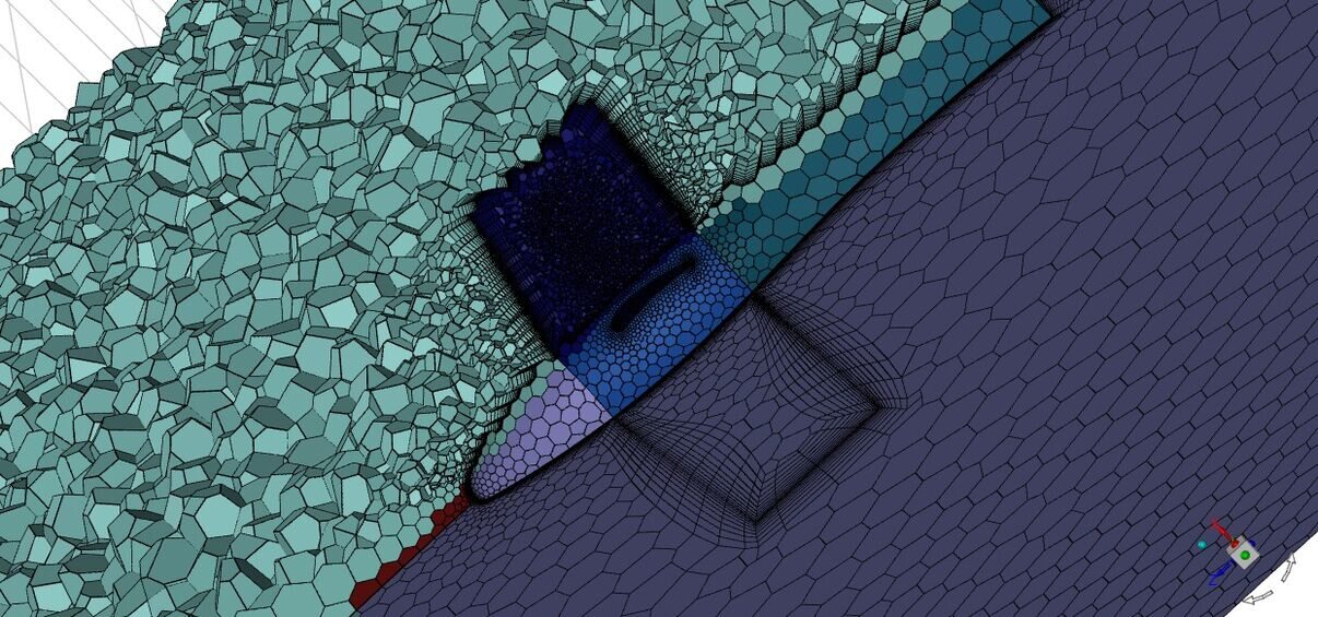
Mesh generation in hull ventilation studies demands a balance between resolution and computational feasibility, given that full-ship models can span tens of meters while critical flow features, such as the gap around a grille or the boundary layer near a hot exhaust pipe, occur at the millimeter to centimeter scale. Engineers typically employ a combination of mesh strategies: coarser elements in open volumes where flow is relatively uniform, progressively refined elements near walls, equipment surfaces, and inlet/outlet boundaries, and localized refinement zones around features of particular interest such as fan inlets or hot spots identified from previous analyses or thermal surveys.
Boundary layer resolution deserves special attention because heat transfer from hot equipment surfaces to the surrounding air is governed by what happens in these thin near-wall regions. Inflation layers, sometimes called prism layers, are built up from solid surfaces to capture the steep velocity and temperature gradients accurately. Getting the first layer thickness and growth rate right directly affects the accuracy of predicted surface temperatures and convective heat transfer coefficients, which in turn drive the overall thermal results that classification societies and clients care about most.
Boundary conditions translate the real-world operating scenario into mathematical inputs the solver can use. Inlet boundaries representing fresh air supply fans are typically defined using mass flow rate or velocity values derived from fan curves and ductwork specifications, along with an appropriate ambient temperature representing the design condition, whether that is a hot tropical scenario or a cold arctic one. Outlet boundaries representing exhaust fans or natural relief openings are often set as pressure outlets, allowing the solver to determine the resulting flow split naturally based on the internal pressure field rather than forcing an artificial flow distribution.
Heat sources require careful characterization because they are the primary driver of the thermal results everyone is ultimately interested in. Major equipment such as main engines, generators, and exhaust systems are typically modeled as surface heat flux or fixed temperature boundary conditions derived from manufacturer data or measured values from sister vessels. Smaller distributed heat sources, such as electrical panels and lighting, may be lumped into volumetric heat generation terms within relevant zones. The accuracy of these heat load definitions is arguably as important as the mesh quality itself, because even a perfectly resolved flow field will produce misleading thermal results if the underlying heat inputs do not reflect reality.

Turbulence modeling choices round out the model setup, with the selection typically depending on the flow regimes expected and the level of detail required. For most engine room and general compartment ventilation studies, robust two-equation models such as k-omega SST provide a good balance of accuracy and computational cost, capturing both the near-wall behavior important for heat transfer and the larger-scale mixing that determines how well ventilation air penetrates into corners and recesses. For studies focused on external wind effects around superstructures, where flow separation and wake behavior are critical, similar turbulence models are used but often with additional mesh refinement in separation-prone regions such as the leeward side of deckhouses and around mast structures.
3. Interpreting Results and Driving Design Improvements
Once a hull ventilation simulation converges, the real engineering work begins: translating a sea of numerical data into clear, actionable insights that designers and shipyards can act upon. The first and most fundamental output engineers examine is the temperature distribution throughout each compartment, typically visualized as contour plots on horizontal and vertical planes that slice through the space at multiple heights. These plots immediately reveal hot spots, cold zones, and stratification patterns that would be invisible from any single-point temperature reading, and they form the basis for comparing predicted conditions against the maximum allowable temperatures specified by equipment manufacturers and classification rules.
Velocity field visualization complements the thermal results by showing how air actually moves through the space. Streamlines and vector plots reveal whether ventilation air follows the intended path from inlet to outlet, or whether it short-circuits, recirculates in unintended loops, or stagnates in dead zones. A particularly useful technique is overlaying velocity vectors on the temperature contours, which immediately shows the relationship between flow patterns and thermal performance, for example confirming that a hot spot exists precisely because the velocity field shows near-zero airflow in that region despite an apparently adequate overall ventilation rate.

Air change rate verification is a standard deliverable, where the simulation results are post-processed to calculate the effective number of air changes per hour for each compartment based on the actual computed flow rates through inlet and outlet boundaries. This provides a direct comparison against regulatory minimums and design targets, but more importantly, when combined with the velocity and temperature fields, it reveals whether the calculated air change rate is actually achieving effective mixing or merely passing through a limited portion of the compartment volume while the bulk of the air remains comparatively undisturbed.
For studies involving gas dispersion, such as analyzing hazardous area classifications around fuel systems or battery compartments, concentration contours show how a released gas would spread and dilute over time. These results are critical for determining whether ventilation rates are sufficient to keep concentrations below lower flammability limits or toxicity thresholds in the event of a leak, and they often drive decisions about detector placement, ensuring gas sensors are located where concentrations would first become significant rather than in locations the gas might never reach due to local flow patterns.
Pressure distribution results matter both for understanding inter-compartment airflow and for practical considerations such as door operability and noise. Large pressure differentials across a door can make it difficult to open, while unintended negative pressure in a compartment can draw in air, fumes, or moisture from adjacent spaces in ways that compromise both comfort and safety. CFD pressure maps allow engineers to identify these issues early and adjust fan capacities, duct sizing, or relief opening areas before they become problems discovered during sea trials.
When results reveal problems, and they often do on a first iteration, the same CFD model becomes the platform for testing solutions rapidly and cost-effectively. Relocating a supply diffuser, adding a destratification fan, resizing an exhaust duct, or repositioning equipment to improve airflow access can all be evaluated through additional simulation runs without touching physical hardware. This iterative design loop, where each design change is virtually tested before commitment, is where CFD delivers its greatest value, often identifying solutions that would never have been considered through traditional rule-of-thumb design approaches.
Documentation and reporting transform these technical findings into deliverables that serve multiple audiences. A well-structured ventilation report includes executive summaries for project managers, detailed technical results for design engineers, and compliance tables mapping results directly against classification society requirements for surveyors and regulatory reviewers. At Epsilon X Sky, our reports are built to serve as standalone evidence packages that can be submitted directly to classification societies, reducing back-and-forth queries and accelerating the approval process for our clients.
4. How Epsilon X Sky Delivers Hull Ventilation CFD Projects
At Epsilon X Sky, every hull ventilation project begins with a thorough scoping conversation rather than jumping straight into simulation. We work closely with naval architects and shipyard engineers to understand the specific compartments of concern, the regulatory framework governing the vessel class, the operational profile across different routes and seasons, and any known issues from sister vessels or previous designs that should inform our modeling priorities. This upfront alignment ensures that the CFD effort is focused on questions that genuinely matter to the project, rather than producing generic results that look impressive but do not address the client's actual engineering concerns.
Our geometry and meshing workflow leverages ANSYS SpaceClaim and ANSYS Meshing to efficiently process complex shipyard CAD data, with established simplification protocols that strip unnecessary detail while preserving everything relevant to airflow. We maintain a library of validated meshing strategies for common compartment types, engine rooms, battery rooms, cargo holds, and accommodation spaces, allowing us to move from raw CAD to a simulation-ready mesh faster than starting from scratch on every project, without sacrificing the quality controls that ensure mesh independence and solution reliability.

Simulation execution is performed using ANSYS Fluent, with turbulence and heat transfer models selected based on years of experience correlating CFD predictions against real shipboard measurements where such data is available. This experience-driven model selection means our clients are not just getting a generic out-of-the-box simulation, but one tuned based on what we have learned actually correlates well with reality for marine ventilation applications specifically, as opposed to general HVAC or industrial settings where different flow regimes and heat transfer mechanisms dominate.
For projects requiring multiple operating scenarios, such as different ambient temperatures, load conditions, or fan configurations, we structure our simulation matrix to maximize insight per computational hour, often using a baseline high-fidelity case to validate the model setup before running a broader set of parametric cases with streamlined post-processing. This approach allows us to deliver comprehensive envelope studies within practical project timelines and budgets, giving clients confidence that their design has been tested across the conditions it will actually encounter in service rather than just a single best-case scenario.
Collaboration throughout the project is built around interim reviews rather than a single final handoff. We share preliminary visualizations, often through interactive sessions where clients can see flow patterns and temperature fields directly, allowing design teams to provide input on which areas deserve deeper investigation or which design alternatives should be tested. This iterative engagement model means that by the time the final report is delivered, there are no surprises, the results have already been discussed, understood, and where necessary, acted upon through design iterations within the same project scope.
Quality assurance is embedded throughout our process, including mesh sensitivity studies to confirm results are independent of grid resolution, energy and mass balance checks to verify solution convergence beyond simple residual targets, and where possible, comparison against analytical estimates or available field data as a sanity check on absolute values. These checks are documented as part of our deliverables, giving classification societies and regulatory reviewers the confidence that the results represent genuine engineering analysis rather than an unverified solver output.

Looking beyond individual projects, Epsilon X Sky positions hull ventilation CFD as part of a broader simulation-driven design philosophy, where airflow, thermal, structural, and other engineering disciplines inform each other throughout the design process rather than being siloed into separate late-stage checks. Our tagline, Customized Ingenuity for a Smarter Life, reflects this approach: every project is tailored to the specific vessel, client, and operational context, applying engineering ingenuity not as a generic service but as a customized solution that ultimately makes vessels safer, more efficient, and more comfortable for the people who operate and live aboard them.
Share this article